|
The RCX is a programmable, microcontroller-based brick that can simultaneously operate three motors, three sensors, and an infrared serial communications interface. The brick is one of approximately 727 pieces of LEGO® set 9719 Robotics Invention System.
This document is a description of the internals of the RCX, and is organized into the following sections:
Please note that this not an official LEGO® document or web site. LEGO® is a trademark of the LEGO Group, which does not sponsor, authorize, or endorse this document.
In addition, note that this document describes RCX internals as the author understands them. While every effort has been made to ensure that the contents of this document are accurate, the author does not guarantee that any portion of this document is correct. The author cannot be held responsible for any consequences of the use or misuse of the information contained in this document.
This document is currently a work in-progress.
Copyright © 1998, 1999 Kekoa Proudfoot. All
rights reserved.
|
The base system for using the RCX consists of the RCX itself, an infrared transceiver, and a PC. Additional components, such as motors, sensors, and other building elements, combine with the base system to allow the creation of functional autonomous robotic devices.
At the core of the RCX is a Hitachi H8 microcontroller with 32K of external
RAM. The microcontroller is used to control three motors, three sensors,
and an infrared serial communications port. An on-chip, 16K ROM contains a
driver that is run when the RCX is first powered up. The on-chip driver is
extended by downloading 16K of firmware to the RCX. Both the driver and
firmware accept and execute commands from the PC through the IR
communications port. Additionally, user programs are downloaded to the RCX
as byte code and are stored in a 6K region of memory. When instructed to
do so, the firmware interprets and executes the byte code of these
programs.
|
RCX
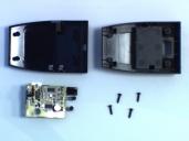
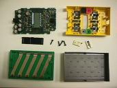
Pictures of a disassembled RCX. To remove the circuit board, open the RCX, remove the four screws, remove the IR shield, then separate the front cover from the circuit board. Release the two battery contacts from the battery side, then slide the circuit board free. Do this at your own risk; if you're not careful there's a chance you'll break something.
Patrick Gili reports that you can also twist the circuit board free without first removing the battery contacts.
I've found that the negative battery contact is somewhat easier to release than the positive one. By removing the negative contact first, then sliding the circuit board free, I am able to remove the positive contact from the circuit board side by inserting a small screwdriver in the slot between the contact and the battery case and gently prying the contact outward and upward. I'm not sure if this technique will work for others; it might be possible only because I have already disassembled my RCX several times.
| The parts, from left to right, starting with the top row: circuit board, front cover; IR shield, screws, battery contacts; battery case, battery cover. Two removable plastic ribs are sitting on the battery case. (1x image) |
|
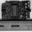
| The top of the circuit board. Two IR LEDs and an IR receiver are on the left, an LCD is in the center, and several capacitors and an adapter socket are on the right. The LCD is covering an LCD controller and a speaker; above and below the LCD are the contacts for the four rubber keys. Twelve clamps rise from the circuit board to mate with the input and output ports on the cover. (1x image, 2x image, part numbers) |
|
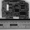
| The bottom of the circuit board. The large square chip is the microcontroller, the chip below that is a RAM. The large chip in the middle is a bank of flip flops, the small chip above that is a bank of NAND gates. Peter Phillips sent word that the three identical chips on the left half of the board are indeed motor controllers. (1x image, 2x image, part numbers) |
|
IR Transceiver
It is also possible to disassemble the IR transceiver. Simply remove the four screws and lift off the back cover, making sure to move the battery spring out of the way.
| IR transceiver parts. From left to right, starting with the top row: front cover, back cover; circuit board, screws. The front cover doubles as an IR filter. (1x image) |
|
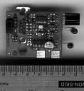
| The top of the circuit board in the IR transceiver. A switch and a 6.7 ohm resistor are on the left, the two chips in the middle are banks of NAND gates, and the grey circle in the lower right is a voltage regulator. The white rectangle below the chip in the upper middle is a green LED, and hanging off the right side of the chip are the IR receiver and two identical IR LEDs. The DB-9 serial connector is on the opposite side of the circuit board. (1x image, 2x image) |
|
Cables
The cable to connect the IR transceiver to your PC is a null modem cable that contains six wires, of which only five are used. With the larger row on top, the holes of each connector are numbered from right to left starting with the top row. Pins inserted into these holes are joined by the cable to pins inserted into the holes of the opposite connector as follows:
| Pin | To | Name | Description |
|---|---|---|---|
| 2 | 3 | RD | Receive Data |
| 3 | 2 | TD | Transmit Data |
| 5 | 5 | SG | Signal Ground |
| 7 | 8 | RTS | Ready To Send |
| 8 | 7 | CTS | Clear To Send |
Pin 4 connects to pin 4 but is unused; pins 1, 6, and 9 have no connection.
The RTS/CTS signals are not used for flow control. Instead, they are used by the PC to check whether or not the transceiver is connected. The transceiver wires CTS and RTS together; the PC checks for the transceiver by asserting and deasserting RTS. If it sees that CTS tracks RTS, then it assumes that the device sitting on the serial port is the transceiver.
In case you're new to this sort of thing, to attach the IR transceiver to a
Mac, you can use the usual combination of a DIN-8 to DB-25 serial cable
coupled to a DB-25 to DB-9 adapter. If you try this, you might not be able
to get the RTS and CTS signals to function properly; this shouldn't be a
problem if you're writing or using custom software.
|
Encoding
The bit encoding and basic packet structure of the serial protocol was originally described by Dave Baum in a message posted to the lego-robotics mailing list. This section summarizes and expands on that description.
My notes as of Nov 10 1998, which roughly outline some of the details of the serial protocol, the byte code interpreter, and other parts of the rcx:
Basic packet format Immediately after packet header is opcode byte Remainder is data for opcode PC sends query opcode RCX reply opcode is always ~query opcode RCX completely ignores messages that have invalid packet checksums Messages sent by PC seem to alternate between having 0x08 set and not set This 0x08 bit is a sequence bit only in one special case RCX never executes same exact opcode twice in a row Second and beyond are dropped But the same reply that was sent the first time is sent again Toggle 0x08 bit to make sure same opcode twice in a row is accepted Sometimes packets start with aa ff 00 instead of 55 ff 00 Sometimes packets start with stranger things too Strange packet headers are most likely due to receiver bias and timing errors Special packet data 01 02 03 04 ff fe fd fc sent when RCX is not listening Tower echos commands sent by PC Sometimes an ff appears a few seconds after a message is received Chris Osborn explained that ff is caused by tower powering down Confirmed this observation Friederich Prinz notes 55 ff 00 is not strictly necessary when sending to RCX He uses ff 00 instead I verified that this agrees with the ROM pseudocode Any string of 55s, ffs, and 00s (or the empty string) works as a header |
Byte Code Interpreter Tasks and subroutines 8 subroutines per program 10 tasks per program Mindstorms software does not seem to use subroutines, only tasks My Commands seem to be inlined regardless of how many times they are used But subroutines are there to use if you want to make use of them yourself Memory map The memory map contains addresses, stored as big endian shorts. The layout is as follows: index description 00-07 prog 0 subs 0-7 start 08-15 prog 1 subs 0-7 start 16-23 prog 2 subs 0-7 start 24-31 prog 3 subs 0-7 start 32-39 prog 4 subs 0-7 start 40-49 prog 0 tasks 0-9 start 50-59 prog 1 tasks 0-9 start 60-69 prog 2 tasks 0-9 start 70-79 prog 3 tasks 0-9 start 80-89 prog 4 tasks 0-9 start 90 datalog start 91 datalog next 92 first free 93 last valid The addresses increase monotonically, so the end of the space allocated for one item can usually be found by looking at the next address in the map. The first address is ceba and the last address is e6b9. Therefore the total size of user memory is exactly 6K. The memory map says something about how user memory is managed inside the rcx. Whenever an item is added, later items are moved up in memory to make room for the new item. Whenever an item is deleted, later items are moved down in memory to consolidate free space. An empty subroutine takes up one byte of space, while an empty task takes up zero bytes of space. When a start download or set datalog command is sent, it might fail with an error code related to amount of memory. Memory map was used to confirm this. Sources Many commands take parameters as source and argument Sources are like addressing modes, many of which are unconventional: 0 variable <0..31> 1 timers <0,1,2,3> 2 immediate 3 motor state <0,1,2> <0x07=power 0x08=fwd 0x40=off 0x80=on 0x00=float> 4 random <return value is in 0 to argument, inclusive> 5 reserved 6 reserved 7 reserved 8 current program number 9 sensors <0,1,2> 10 sensor type <0,1,2> 11 sensor mode <0,1,2> 12 raw sensor value <0,1,2> 13 boolean sensor value <0,1,2> 14 minutes on clock/watch <0> 15 message <0> Sources 5, 6, and 7 are never valid. Do not use them. They are reserved for Cybermaster. Loops The byte code interpreter seems to include a stack of loop counters The maximum loop counter stack depth is four Set loop counter pushes stack down and sets the top value Decrement loop counter and branch decrements counter on top of stack Decrement before test When top counter is less than zero, stack is popped and branch is taken Otherwise branch is not taken Decrement loop counter and branch only branches forward But you can use a second branch to go backwards Sounds Sounds seem to be buffered, with buffer size around eight Sounds are lost when buffer is full Sounds seem to be asynchronous, meaning their calls seem to return immediately Programs Programs use the same opcodes as sent over serial cable PC opcodes which query state in RCX seem to be treated as noops in programs All other PC to RCX opcodes seem to work, which is surprising Unrecognized opcodes cause the program (task?) to halt Program (task?) also halts when current address is not in valid memory range Valid memory range specified in memory map Still need to describe how to compose and download a program |
|
The table in this section gives a brief overview of the opcodes that make up the RCX byte code and is an index into the RCX Opcode Reference, where more information about the opcodes can be found. An alphabetical opcode index is also available.
In the table below, the valid contexts of each opcode are listed under the Modes heading. A P indicates a request sent from the PC to the RCX, an R indicates a reply from the RCX to the PC, and a C indicates a command that may be used in byte code.
| Opcode | Modes | Name | Encoding | Notes | ||
|---|---|---|---|---|---|---|
| 10/18 | P | Alive | void | [details] | ||
| 12/1a | P | Get value | byte source byte argument | [details] | ||
| 13/1b | P | C | Set motor power | byte motors byte source byte argument | [details] | |
| 14/1c | P | C | Set variable | byte index byte source short argument | [details] | |
| 15/1d | P | Get versions | byte key[5] | [details] | ||
| 16/1e | R | Set motor direction | void | [details] | ||
| 17/xx | C | Call subroutine | byte subroutine | [details] | ||
| 20/28 | P | Get memory map | void | [details] | ||
| 21/29 | P | C | Set motor on/off | byte code | [details] | |
| 22/2a | P | C | Set time | byte hours byte minutes | [details] | |
| 23/2b | P | C | Play tone | short frequency byte duration | [details] | |
| 24/2c | P | C | Add to variable | byte index byte source short argument | [details] | |
| 25/2d | P | Start task download | byte unknown short task short length | [details] | ||
| 26/2e | R | Clear sensor value | void | [details] | ||
| 27/xx | C | Branch always near | byte offset | [details] | ||
| 30/38 | P | Get battery power | void | [details] | ||
| 31/39 | P | C | Set transmitter range | byte range | [details] | |
| 32/3a | P | C | Set sensor type | byte sensor byte type | [details] | |
| 33/3b | P | C | Set display | byte source short argument | [details] | |
| 34/3c | P | C | Subtract from variable | byte index byte source short argument | [details] | |
| 35/3d | P | Start subroutine download | byte unknown short subroutine short length | [details] | ||
| 36/3e | R | Delete subroutine | void | [details] | ||
| 37/xx | C | Decrement loop counter near | byte offset | [details] | ||
| 40/48 | P | C | Delete all tasks | void | [details] | |
| 42/4a | P | C | Set sensor mode | byte sensor byte code | [details] | |
| 43/xx | C | Wait | byte source short argument | [details] | ||
| 44/4c | P | C | Divide variable | byte index byte source short argument | [details] | |
| 45/4d | P | Transfer data | short index short length byte data[length] byte checksum | [details] | ||
| 46/4e | R | Set power down delay | void | [details] | ||
| 50/58 | P | C | Stop all tasks | void | [details] | |
| 51/59 | P | C | Play sound | byte sound | [details] | |
| 52/5a | P | C | Set datalog size | short size | [details] | |
| 52/5a | R | Unlock firmware | byte data[25] | [details] | ||
| 53/5b | R | Upload datalog | dlrec data[length] | [details] | ||
| 54/5c | P | C | Multiply variable | byte index byte source short argument | [details] | |
| 56/5e | R | Clear timer | void | [details] | ||
| 60/68 | P | C | Power off | void | [details] | |
| 61/69 | P | C | Delete task | byte task | [details] | |
| 62/6a | P | C | Datalog next | byte source byte argument | [details] | |
| 63/6b | R | Or variable | void | [details] | ||
| 64/6c | P | C | Sign variable | byte index byte source short argument | [details] | |
| 65/6d | P | C | Delete firmware | byte key[5] | [details] | |
| 66/6e | R | Set program number | void | [details] | ||
| 70/78 | P | C | Delete all subroutines | void | [details] | |
| 71/79 | P | C | Start task | byte task | [details] | |
| 72/xx | C | Branch always far | byte offset byte extension | [details] | ||
| 73/7b | R | And variable | void | [details] | ||
| 74/7c | P | C | Absolute value | byte index byte source short argument | [details] | |
| 75/7d | P | Start firmware download | short address short checksum byte unknown | [details] | ||
| 76/7e | R | Stop task | void | [details] | ||
| 81/89 | P | C | Stop task | byte task | [details] | |
| 82/8a | R | Start firmware download | byte errorcode | [details] | ||
| 82/xx | C | Set loop counter | byte source byte argument | [details] | ||
| 83/8b | R | Absolute value | void | [details] | ||
| 84/8c | P | C | And variable | byte index byte source byte argument | [details] | |
| 85/xx | C | Test and branch near | byte opsrc1 byte src2 short arg1 byte arg2 byte offset | [details] | ||
| 86/8e | R | Start task | void | [details] | ||
| 87/8f | R | Delete all subroutines | void | [details] | ||
| 90/xx | C | Clear message | void | [details] | ||
| 91/99 | P | C | Set program number | byte program | [details] | |
| 92/9a |   | R | Delete firmware | void | [details] | |
| 92/xx | C | Decrement loop counter far | short offset | [details] | ||
| 93/9b | R | Sign variable | void | [details] | ||
| 94/9c | P | C | Or variable | byte index byte source byte argument | [details] | |
| 95/9d | R | Datalog next | byte errorcode | [details] | ||
| 95/xx | C | Test and branch far | byte opsrc1 byte src2 short arg1 byte arg2 short offset | [details] | ||
| 96/9e | R | Delete task | void | [details] | ||
| 97/9f | R | Power off | void | [details] | ||
| a1/a9 | P | C | Clear timer | byte timer | [details] | |
| a3/ab | R | Multiply variable | void | [details] | ||
| a4/ac | P | Upload datalog | short first short count | [details] | ||
| a5/ad | P | Unlock firmware | byte key[5] | [details] | ||
| a5/ad | R | Set datalog size | byte errorcode | [details] | ||
| a6/ae | R | Play sound | void | [details] | ||
| a7/af | R | Stop all tasks | void | [details] | ||
| b1/b9 | P | C | Set power down delay | byte minutes | [details] | |
| b2/ba | R | Transfer data | byte errorcode | [details] | ||
| b2/xx | C | Send message | byte source byte argument | [details] | ||
| b3/bb | R | Divide variable | void | [details] | ||
| b5/bd | R | Set sensor mode | void | [details] | ||
| b7/bf | R | Delete all tasks | void | [details] | ||
| c1/c9 | P | C | Delete subroutine | byte subroutine | [details] | |
| c2/ca | R | Start subroutine download | byte errorcode | [details] | ||
| c3/cb | R | Subtract from variable | void | [details] | ||
| c4/cc | R | Set display | void | [details] | ||
| c5/cd | R | Set sensor type | void | [details] | ||
| c6/ce | R | Set transmitter range | void | [details] | ||
| c7/cf | R | Get battery power | short millivolts | [details] | ||
| d1/d9 | P | C | Clear sensor value | byte sensor | [details] | |
| d2/da | R | Start task download | byte errorcode | [details] | ||
| d3/db | R | Add to variable | void | [details] | ||
| d4/dc | R | Play tone | void | [details] | ||
| d5/dd | R | Set time | void | [details] | ||
| d6/de | R | Set motor on/off | void | [details] | ||
| d7/df | R | Get memory map | short map[94] | [details] | ||
| e1/e9 | P | C | Set motor direction | byte code | [details] | |
| e2/ea | R | Get versions | short rom[2] short firmware[2] | [details] | ||
| e3/eb | R | Set variable | void | [details] | ||
| e4/ec | R | Set motor power | void | [details] | ||
| e5/ed | R | Get value | short value | [details] | ||
| e7/ef | R | Alive | void | [details] | ||
| f7/xx | P | C | Set message | byte message | [details] |
|
A complete image of the ROM on board the microcontroller was obtained on Oct 1 1998. This section contains my notes on the ROM image, as of Apr 25 1999.
For now, you can find instructions for obtaining a ROM image here.
On Oct 29 1998 I released some original replacement firmware. If you're interested in this, the code is called first.s, and the S-record data is called first.srec. The firmware does nothing in particular except respond to the power key and light up the display. After loading first.srec (either by using the OCX or by doing the rename thing), you'll need to turn on your RCX with the batteries removed before restoring the original firmware. Use first.srec at your own risk.
On Dec 15 1998 I started working on a separate ROM reference document and a very small ROM interface library that allows you to easily create programs that call ROM functions from C compiled using GCC. The interface library was necessary to test the reference document; however, I expect that it will make an excellent base point for building up source for a non-Lego version of the 0309 firmware, should anyone want to try that.
High level notes
As expected, the ROM contains low-level routines for driving the RCX
It controls the on/off/stall signals sent to the motor drivers
It manages pulse width modulation for the motors
It manages the A/D conversion for the inputs
It manages talking to the serial port
It manages the speaker
It checks messages at a low level
Checks opcodes to make sure they have the right number of bytes
Checks checksum too
Handles opcode 45 specially
ROM calls first address of firmware, firmware never returns
Once firmware is started, it calls ROM to do things
The init_timer function at 3b9a sets up an OCIA handler
OCIA handler called every 1/1000th sec
This is the main asynchronous ROM routine
ROM communicates with firmware using two methods
Two data structures passed to init_timer are updated by ROM
ROM functions communicate data between ROM and firmware
Data at pointers passed to init_serial also updated
The ROM can be completely overridden, if you like
Just don't call init_timer and the H8 is all yours
You will probably still want to use some H8 routines, however
The LCD routines especially
The init routine is at 03ae
Clears some memory, specifically ee5e-f000
Copies default interrupt handler 046a into RAM interrupt vector table
Calls main at 0580
The main routine is at 0580
If main ever returns, ROM loops forever
ROM interrupt handlers call addresses that are stored in RAM
This allows all interrupt handlers to be overridden
Prudence on LEGO's part, perhaps
But it also allows for some serious hacking (!)
By overriding a handlers you can drive the H8 at a very low level
This is probably more important than you think it is
The default interrupt handler is 046a
Default handler does nothing but return
All handlers are initialized to this on reset
Real interrupt handlers are set after reset
IRQ0 set to 1ab8 at 1ac0
IRQ1 set to 294a at 2968
TEI set to 2a84 at 31d4
TXI set to 2a9c at 31dc
RXI set to 2c10 at 31e4
ERI set to 30a4 at 31ec
OCIA set to 36ba at 3c1c
A/D set to 3b74 at 3c24
And that's all of them as far as the ROM is concerned
Vector at fd90 is 03ae (init) if firmware loaded, 046a (default) otherwise
Other notes
Paul Haas was right about messages being grouped and parsed by lower 3 bits
Tramm Nelson used to be reverse engineering the ROM from the firmware side
He apparently also had gcc working, at least somewhat
He also mentioned something about a web page, but gave no URL
Matt Cross has also been doing interesting work with the firmware
He mentioned switch on opcode in firmware
Paul Haas had a few interesting comments what Matt had to say
Other people offered advice on how to get a few tools set up
Kenneth Dyke was the first person to describe how to compile gnu binutils
Craig Trader was the first to describe how to use the disassembler
I figured out how to use the assembler on my own
Then I disassembled my code and edited the output bytes in emacs (!)
Thanks to Matt Cross and Mark Salter I have gotten binutils to work
H8300 binutils for IRIX are busted, I now run binutils under Solaris
Technique is to assemble a .o, then link, as described by Mark Salter
But Matt adds that you must convert branch target addresses to labels
This fixes a sign extension problem with branch target addresses
Allen Martin, Jon Andersson, and Bob Wind have all posted interesting info
Allen came up with a method similar to Matt's for recompiling firmware
He added the idea of testing reassembly by inserting nops
Jon posted some rough notes from looking at the ROM disassembly
Bob Wind posted a description of cc00 firmware data structure
I came up with a similar list independently, which is included below
Matt Cross found out some interesting things about the 070c ROM routine
Matt explained it is a state machine
My conclusion is that it drives the RCX when firmware is not loaded
Markus Noga has been doing a lot of interesting work with GCC
He is also looking into interesting ways to bypass/rewrite ROM routines
A bit lower level than I imagined going
An interesting way to extend things
I know I'm forgetting somebody here
Vadim mentioned I had used 0x80 instead of 0x08
Fixed this
Also fixed mention of lsb when I meant lower 3 bits
|
Notes on addresses:
ROM vectors/data:
0000 - short array [37], interrupt vectors
004a - short array [8], math function vectors
005a - short array [83], unused
0100 - short array [24], default RAM interrupt vectors, copied to @fd90[24]
For the list of functions below, be sure to also check the lists at the
bottom. The two lists are no longer in sync.
ROM code:
0130 - @@74 handler, r6 = r6 * r5 (16b multiply)
014a - @@76 handler, r6 = r6 % r5 (16b modulo, unsigned)
0156 - @@82 handler, r6 = r6 / r5 (16b divide, signed)
0188 - @@80 handler, r6 = r6 % r5 (16b modulo, signed)
01be - @@78 handler, r6 = r6 / r5 (16b divide, unsigned)
01fe - @@84 handler, r5r6 = r5r6 * r3r4 (32b multiply)
026e - @@88 routine, r5r6 = r5r6 / r3r4 (32b divide, signed)
0306 - @@86 handler, r5r6 = r5r6 / r3r4 (32b divide, unsigned)
03ae - init - see notes, below
03ca - init memory - clear [ee53,f000), copy RAM interrupt vectors into place
042a - copy memory - copy [r0,r1) to [r2,r2+r1-r0)
0436 - clear memory - clear [r0,r1)
0442 - init control registers - see notes, below
046a - default interrupt handler - does nothing but return
046c - NMI dispatch - all of these dispatches jsr to an address stored in RAM
0478 - IRQ0 dispatch
0484 - IRQ1 dispatch
0490 - IRQ2 dispatch
049c - IC1A dispatch
04a8 - IC1B dispatch
04b4 - IC1C dispatch
04c0 - IC1D dispatch
04cc - OC1A dispatch
04d8 - OC1B dispatch
04e4 - FOV1 dispatch
04f0 - CMI0A dispatch
04fc - CMI0B dispatch
0508 - OVI0 dispatch
0514 - CMI1A dispatch
0520 - CMI1B dispatch
052c - OVI1 dispatch
0538 - ERI dispatch
0544 - RXI dispatch
0550 - TXI dispatch
055c - TEI dispatch
0568 - A/D dispatch
0574 - WOVF dispatch
0580 - void rom_main (void)
0688 - void rom_init_handlers (r6=dataptr)
070c - void rom_update (r6=dataptr)
0d18 - void rom_shutdown_handlers (r6=unuseddataptr)
0d3c - void rom_power_off (void)
0d44 - void rom_init_program (r6=unuseddataptr)
0d8c<- void rom_program_update? (r6=dataptr)
1446.- void rom_program_stop? (r6=unuseddataptr)
148a - void do_nothing (void)
1498 = void init_sensors (void) [@827e, in first handler init]
14c0 = void read_sensor (r6=1000+sensorindex, sp0=sensorstruct *type) [@831a]
1946 = void set_sensor_active (r6=1000+sensorindex) [@82be]
19c4 = void set_sensor_passive (r6=1000+sensorindex) [@82cc]
1a1e - void do_nothing (void), never called
1a22 = void shutdown_sensors (void) [@83ba]
1a4a = void do_nothing [init_motors] (void) [@8430]
1a4e = void control_motor (r6=2000+motorindex, sp0=mode, sp1=power)
1ab0 - void do_nothing (void), never called
1ab4 = void do_nothing [shutdown_motors] (void) [@85e0]
1ab8 - IRQ0 handler - does nothing except rts
1aba = void init_buttons_and_lcd (void) [@8612]
1b32 = void play_view_button_sound (r6=301e) [@8698]
1b62 = void set_lcd_segment (short code)
1e4a = void clear_lcd_segment (short code)
1fb6 = void read_buttons (short code=0x3000, short *ptr)
1ff2>= void set_lcd_number (short code, short value, short pointcode)
27ac = void clear_display (void)
27c8 = void refresh_display (void)
27f0 - void do_nothing (void)
27f4 = void shutdown_buttons_and_lcd (void) [@8d00]
283c - void write_lcd_outputs (r6=short *lcdaddr)
294a - IRQ1 handler
2964 = void init_power (void) [for fourth handler]
299a = void play_system_sound (short code, short sound)
29f2 = void get_power_status (short code, short *ptr)
29f2 = void get_on_off_key_state (short code=0x4000, short *ptr)
29f2 = void get_battery_voltage (short code=0x4001, short *ptr)
2a32 - void set_on_off_key_output_low (short code=0x4002), never called
2a48 - void set_on_off_key_output_high (short code=0x4002), never called
2a5e - void do_nothing (void) returns 0, never called
2a62 = void shutdown_power (void), turns power off
2a84 - TEI handler
2a9c - TXI handler
2c10 - RXI handler
30a4 - ERI handler
30d0 = void init_serial (r6=cc00+4, sp0=cc00+6, sp1=1, sp2=1) [@8f62]
3250 = void set_range_long (short code=0x1770)
3266 = void set_range_short (short code=0x1770)
327c = play_sound_or_set_data_pointer (short code, short param0, short param1)
339a = void reset_internal_minute_timer (r6=0x1774) // code is ignored?
33b0 = void receive_data (void *data, byte maxlen, byte *length) [@92b2]
3426 = void check_for_data (byte *valid, byte **nextbyte)
343e = byte send_data (short code, byte opcode, byte *data, short len)
3636 = void shutdown_serial (void)
3692 = void init_port_6_bit_3 (void), nobody knows what port 6 bit 3 does
36a6 = void do_nothing (void)
36aa = void shutdown_port_6_bit_3 (void), nobody knows what port 6 bit 3 does
36ba - OCIA handler
3b74 - A/D handler
3b9a = void init_timer (r6=timerdataptr (40b), sp0=dispatchdataptr (6b))
3ccc = void get_sound_playing_flag (short code=0x700c, byte *ptr) ?
3ce6 - void control_motor_2 (r6=code=7001+motorindex, sp0=motorcode) [see 1a4e]
3de0 = void control_output (short code, short sp0, short sp1, short sp2)
3e9e - void clear_sensor_and_timer_data (short code, byte param)
3ed0 - void do_nothing (void) [never called]
3ed4 = void shutdown_timer (void)
ROM data:
3f12 - byte array [26], "Do you byte, when I knock?"
3f2c - byte array [25], "Just a bit off the block!"
3f45 - byte, unused, 0
3f46 - byte array [8], sound 0 data // sound data has 3 sections
3f4e - byte array [14], sound 1 data // no indication of sections here though
3f5c - byte array [32], sound 2 data
3f7c - byte array [32], sound 3 data
3f9c - byte array [6], sound 4, 6 data
3fa2 - byte array [16], sound 5 data
3fc2 - byte array [8], motor pwm waveforms
3fca - byte array [54], unused, all ff
The codes passed in r6 to some ROM routines seem to be organized
Why are they even there? Maybe as a sanity check?
Maybe the numbers relate to the function or handler?
High nibbles are category/handler id
Low nibbles are function index
This is looking to be more and more likely
C prototypes are used for functions whose interface I understand completely
Parameters for these are as follows
First parameter in r6
Second parameter at offset sp+0 before call
Third parameter at offset sp+2 before call
etc.
Not sure about return values
Some functions return 0 in r6, and it's not clear if they're void or not
For 14c0, sensorstruct is defined in 828c function description, below
Firmware code:
Each handler has three functions - an init, a run, and a stop function
Main loop state stored in r4l
0=init, 1=stop, 3=run, 4=sleep, 1f=battery low
The six handlers are:
1 sensors
2 motors
3 buttons and display
4 power and on/off button
5 interpreter
6 turns on/off bit 3 of p6ddr at init/stop
8000 - firmware init and main loop
823e - first handler init (sensors)
828c - first handler main (sensors)
83b6 - first handler stop (sensors)
83c6 - second handler init (motors)
8440 - second handler main (motors)
85dc - second handler stop (motors)
85ec - third handler init (buttons/display)
863c - third handler main (buttons/display)
8cf4 - third handler stop (buttons/display)
8d0c - fourth handler init (power/on-off)
8d74 - fourth handler main (power/on-off)
8f2a - fourth handler stop (power/on-off)
8f3a - fifth handler init (interpreter)
90d2 - fifth handler main (interpreter)
bc2c - fifth handler stop (interpreter)
bc76 - modify memory map (r6=op,sp0=index,sp1=len,sp2=ptr), r6=retval (0=fail)
bdc0 - sixth handler init (port 6 bit 3) (what is this for?)
bdde - sixth handler main (port 6 bit 3) (what is this for?)
be00 - sixth handler stop (port 6 bit 3) (what is this for?)
Firmware data - the struct (or global memory area) starts at cc00:
cc00 - firmware data, (r+00 indicates offset from register r = cc00)
r+00 - byte, dispatch state, first handler, sensors?
r+01 - byte, dispatch state, second handler, motors
r+02 - byte, dispatch state, third handler, display? buttons?
r+03 - byte, dispatch state, fourth handler, power
r+04 - byte, dispatch state, fifth handler, interpreter
r+05 - byte, dispatch state, sixth handler
r+06 R+00 - word, serial receive reset counter, also start of ROM data struct
r+08 R+02 - word array[4], timer value, in 1/10ths sec
r+10 R+0a - word, minutes on clock/watch
r+12 R+0c - word, minutes to power off
r+14 R+0e - word array[10], per task wake up delay, in 1/100ths sec
r+28 R+22 - word array[3], motor handler wake up counters, in ms
r+2e R+28 - 3B?, unused?
r+31 - byte, program changed flag
r+32 - byte, view button down flag?
r+33 - byte, power on flag, firmware turns RCX off if this goes to zero
r+34 - byte, can run flag (there is code to run)
r+35 - byte, run button state (0=stopped, 1=running)
r+36 - byte, ready to sleep flag (1=go to sleep)
r+37 - byte, firmware delete flag, 0=starting, 1=delete, 2=running
r+38 - byte array[3], sensor type
r+3b - byte array[3], sensor mode
r+3e - word array[3], sensor raw values
r+44 - word array[3], sensor values
r+4a - byte array[3], boolean sensor values
r+4d - byte array[3], real motor state (0x80=on,0x40=off,0x08=fwd,0x07=power)
r+50 - byte array[3], temp motor state (r+4d bits + 0x30=activate)
r+53 - byte array[3], motor state (only for returning by query?)
r+56 - byte, transmitter in use flag (0=not in use, 1=in use) - affects display
r+57 - byte, transmitter range (0=short, 1=long)
r+58 - word, data transfer address
r+5a - word, battery power, in millivolts, initially set to 9V at 8d22
r+5c - byte, current display (0=watch,1-3=sensors,4-6=motors)
r+5d - byte, displayed program number
r+5e - word, power down delay
r+60 - byte, sensor ready flag (0 if sensor mode/type changed, 1 when ready)
r+61 - byte, amount of datalog filled, in fourths, 4=full? or does 5=full?
r+62 - byte, temp motor counter (units unknown)
r+63 - byte, show upload status bar
r+64 - byte, battery low, normally 0, 1 if battery power <= 189c (6300 mV)
cc65 - byte, unused padding?
cc66 - word, handler pointer 1, set to 828c by 8000
cc68 - word, handler pointer 2, set to 8440 by 8000
cc6a - word, handler pointer 3, set to 863c by 8000
cc6c - word, handler pointer 4, set to 8d74 by 8000
cc6e - word, handler pointer 5, set to 90d2 by 8000
cc70 - word, handler pointer 6, set to bdde by 8000
cc72 - byte, sensor ready again counter
cc73 - byte?, padding?
cc74 - byte array[3], motor direction flags (0x08=fwd)
cc77 - byte array[3], motors stopped flag (1=stopped/floating,0=running)
cc7a - byte, button down state (0x1=run 0x2=view 0x4=prgm)
cc7b - byte, last button state (0x1=run 0x2=view 0x4=prgm)
cc7c - word, walking figure state
cc7e - byte, ? set at 8a8e
cc7f - byte, time decimal point blink state?
cc80 - byte, third handler every-other flag
cc81 - byte, datalog blink state
cc82 - byte, upload status bar count
cc83 - byte, unused padding?
cc84 - word, last data transfer address (used for blinking display)
cc86 - word?, unused padding?
cc88 - word, sum of raw battery voltage samples (sum 0x20 samples for average)
cc8a - byte, count of raw battery voltage samples
cc8b - byte, on/off button state machine, a=up, b=down, c=up2, d=down2
cc8c - byte, on/off button debounce counter
cc8d - byte, unused padding?
cc8e - byte array[10], program 0 in subroutine flag, bit index is sub
cc98 - byte array[10], program 1 in subroutine flag, bit index is sub
cca2 - byte array[10], program 2 in subroutine flag, bit index is sub
ccac - byte array[10], program 3 in subroutine flag, bit index is sub
ccb6 - byte array[10], program 4 in subroutine flag, bit index is sub
ccc0 - byte, current task
ccc1 - byte, last received opcode from serial connection
ccc2 - byte, transfer in progress
ccc3 - byte, running flag (run button says to run code)
ccc4 - word, program number
ccc6 - word array[32], variables 0-31
cd06 - byte, last message received
cd07 - byte, unused padding?
cd08 - word, random number state
cd0a - byte, reply valid (0=not valid, 1=send)
cd0b - byte, reply length
cd0c - byte, reply opcode (cd0c is really byte array[16])
cd0d - byte array[15], remainder of reply
cd1c - byte, transfer data next expected index
cd1d - byte, transfer data status, 0x80=set if task, 0x7f=task/sub number
cd1e - word, last d2 data
cd20 - byte, send message after parsing flag (0=no send, 5=send)
cd21 - byte, unused padding?
cd22 - word array[8], program 0 subroutine start addrs (raw memory addr)
cd32 - word array[8], program 1 subroutine start addrs
cd42 - word array[8], program 2 subroutine start addrs
cd52 - word array[8], program 3 subroutine start addrs
cd62 - word array[8], program 4 subroutine start addrs
cd72 - word array[10], program 0 task start addrs (raw memory addr)
cd86 - word array[10], program 1 task start addrs (initially cee2)
cd9a - word array[10], program 2 task start addrs
cdae - word array[10], program 3 task start addrs
cdc2 - word array[10], program 4 task start addrs
cdd6 - word, datalog start
cdd8 - word, datalog next
cdda - word, first free address
cddc - word, last valid address
cdde - word array[10], current program program counters (raw memory addr)
cdf2 - word array[10], program 0 subroutine return addrs (raw memory addr)
ce06 - word array[10], program 1 subroutine return addrs (raw memory addr)
ce1a - word array[10], program 2 subroutine return addrs (raw memory addr)
ce2e - word array[10], program 3 subroutine return addrs (raw memory addr)
ce42 - word array[10], program 4 subroutine return addrs (raw memory addr)
ce56 - byte array[10], program 0 task status (0=invalid,1=valid,2=running)
ce60 - byte array[10], program 1 task status (3=waiting)
ce6a - byte array[10], program 2 task status
ce74 - byte array[10], program 3 task status
ce7e - byte array[10], program 4 task status
ce88 - byte array[10][4], task loop counters, 4 per task
ceb0 - byte array[10], loop counter depth
ceba - byte array[6144], program data
e6ba - blank space?
ROM data: (okay to use when firmware loaded)
before ef00: zero when firmware loaded, because firmware zeros cc00-efff
ee5e - word, rom main loop state, 0=restart, 8=off, d=run, 13=run firmware
ee60 - word, data transfer address
ee62 - word, pointer to firmware start
ee64 - dispatch data, plus padding, ee64 is sensor and serial run flag
ee74 R+00 - word, serial receive reset counter, also start of ROM timer data?
ee76 R+02 - word array[4], timer value
ee7e R+0a - word, minutes on clock/watch
ee80 R+0c - word, minutes to power off
ee82 R+0e - word array[10], per task wakeup delay, in 1/100ths sec
ee96 R+22 - word array[3], motor counters?
ee9c - 24B, unused padding so ROM timer data is 64B?
eeb4 - byte, rom ready to sleep
eeb5 - byte, unused padding?
eeb6 - byte array[64], send packet data
eef6 - byte array[10], receive packet data
ef06 - byte, rom update funtion state
ef07 - byte, rom on/off key state
ef08 - word, last data transfer address
ef0a - word, transfer data index
ef0c - byte, last received opcode
ef0d - byte, send packet length
ef0e - byte, on/off key debounce
ef0f - byte, unused?
ef10 - byte, set to 0 in 0d44, also start of rom program data
ef11 - byte, ?
ef12 - byte, set to 0 in 0d44
ef13 - byte, set to 0 in 0d44
ef14 - 6B, ?
ef1a - byte, set to a in 0d44
ef1b - byte, set to 80 in 0d44
ef1c - 6B, ?
ef22 - byte, set to 0 in 0d44
ef23 - byte, set to 0 in 0d44
ef24 - 6B, ?
ef2a - byte, set to 0 in 0d44 and 1446
ef2b - byte, set to 0 in 1446
ef2c - byte, set to 0 in 0d44
ef2d - byte, set to 0 in 0d44 and 1446
ef2e - word, set to ffff at 0d3c
ef30 - byte, ?
ef32 - byte array [3], angle previous state
ef35 - byte array [3], edge/pulse inited flag
ef38 - byte array [3], edge/pulse debounce counter
ef3b - byte array [3], pulse edge counter, also end of rom program data?
More ROM data: (volatile when ROM functions in use)
ef3e - byte array[15], set to 0 at 1b1c // output for display?, contains ef43
ef43 - byte array[10], output to display in 1b62, part of array[15] at ef3e)
ef4e - byte, download/upload counter for display in 1b62 (0..5)
ef4f - byte, datalog count for display in 1b62 (0..4)
ef50 - byte, use packet header flag
ef51 - byte, use complements flag
ef52 - byte array[64], outgoing packet data (for short packets)
ef92 - byte, outgoing packet data index
ef93 - byte, tranmitting flag, 4f=not tranmitting, 13=transmitting
ef94 - word, outgoing packet type (1775=short, 1776=long)
ef96 - word, outgoing packet length remaining
ef98 - word, outgoing packet data pointer (for long packets)
ef9a - byte, outgoing packet send state
ef9b - byte, outgoing packet opcode and checksum (for long packets)
ef9c - byte, outgoing packet data complement state
ef9d - byte array[16], receive packet data
efad - byte, unused?
efae - word, incoming data pointer
efb0 - byte, receive data index
efb1 - byte, unpack data index
efb2 - byte, receive state, 2=ready 3=regular 4=done 5=opfivetail 6=opfivehead
efb3 - byte, receive expect complement
efb4 - word, data pointer, =cc06 for firmware
efb6 - byte, valid incoming data flag
efb8 - word, data pointer, serial handler run flag, =ee64 ROM, =cc04 firmware
efba - byte, last received byte (ff if last was complement or invalid)
efbc - word, transfer data sequence number, set to ffff for new transfers
efbe - byte, receive checksum
efbf - byte, receive data checksum (for opcode 45)
efc0 - byte, receive length remaining (excludes complements)
efc1 - byte, current receive byte
efc2 - word, receive data length remaining (for opcode 45)
efc4 - word, saved incoming data pointer (for resent transfer data packets)
efc6 - word, data pointer, set by 3b9a, =ee74 for ROM, =cc06 for firmware
efc8 - word, data pointer, dispatch array, =ee64 for ROM, =cc00 for firmware
efca - byte, motor output bits, unmodulated
efcb - byte, motor 0 pwm waveform, rotates right
efcc - byte, motor 1 pwm waveform, rotates right
efcd - byte, motor 2 pwm waveform, rotates right
efce - byte, motor output bits, modulated by motor waveforms
efcf - byte, millisecond counter 0, counts to 30 ms, divides timer to 1/100 sec
efd0 - byte, millisecond counter 1, divides timer to 1/10 sec
efd1 - byte, unused?
efd2 - word, millisecond counter 2, divides timer to 60 sec
efd4 - byte, millisecond counter 3, divides timer to 130 ms
efd5 - byte, sensor output on port 6, used after a/d conversion
efd6 - byte, set to 1 by 3b9a, tail index for sound queues
efd7 - byte, set to 1 by 3b9a, head index for sound queues
efd8 - byte array[10], sound data period byte queue 0=pause,1=sound,>1=tone
efe2 - byte array[10], sound data count byte queue
efec - byte array[10], sound data control byte queue
eff6 - byte, sound duration remaining counter, in 1/100 sec
eff8 - word, pointer to sound data, pitch period byte
effa - word, pointer to sound data, duration byte, in 1/100 sec
effc - word, pointer to sound data, control byte (related to octave)
effe - byte, sound data pointers in use flag (see eff8, effa, effc)
efff - byte, sound playing flag
f000 - byte, motor control word, ROM sets to @efca or @efce
Note: Motors are memory mapped to the ranges [f000,fb7f] and [ff80,ff87].
Writes to addresses in these ranges affect the motors. There is also
off-chip memory backing these addresses, so it's possible to use this
memory with the caveat that writes will change the motor state. One
possible use is to store code in this memory, since that code will
typically be read-only once written. Note that the range [ff80,ff87] is
accessible using shorter instructions that use 8-bit absolute addressing.
ROM data in on-chip RAM:
fd80 - byte, same as ffb0 (p1ddr), set to ff by 3b9a
fd81 - byte, same as ffb1 (p2ddr), set to ff by 3b9a
fd82 - byte, same as ffb4 (p3ddr), but unused? set to 0 by 3b9a
fd83 - byte, same as ffb5 (p4ddr)
fd84 - byte, same as ffb8 (p5ddr), set to 0 by 3b9a
fd85 - byte, same as ffb9 (p6ddr), set=0 by 3b9a, 0x08 set/clr by 6th handlers
fd86 - byte, same as ffbe (p7pin)
fd87 - byte, unused?
fd88 - word, firmware checksum, set to 0 after firmware deleted
fd8a - word, firmware checksum complement, set to 0 after firmware deleted
fd8c - word, firmware entry point, himem version, maybe just new version?
fd8e - (2B?), unused?
fd90 - word, like a reset vector
fd92 - word, NMI interrupt vector
fd94 - word, IRQ0 interrupt vector
fd96 - word, IRQ1 interrupt vector
fd98 - word, IRQ2 interrupt vector
fd9a - word, ICIA interrupt vector
fd9c - word, ICIB interrupt vector
fd9e - word, ICIC interrupt vector
fda0 - word, ICID interrupt vector
fda2 - word, OCIA interrupt vector, set to 36ba by 3b9a
fda4 - word, OCIB interrupt vector
fda6 - word, FOVI interrupt vector
fda8 - word, CMI0A interrupt vector
fdaa - word, CMI0B interrupt vector
fdac - word, OVI0 interrupt vector
fdae - word, CMI1A interrupt vector
fdb0 - word, CMI1B interrupt vector
fdb2 - word, OVI1 interrupt vector
fdb4 - word, ERI interrupt vector, set to 30a3 at 31ec
fdb6 - word, RXI interrupt vector, set to 2c10 at 31e4
fdb8 - word, TXI interrupt vector, set to 2aac at 31dc
fdba - word, TEI interrupt vector, set to 2a84 at 31d4
fdbc - word, A/D interrupt vector, set to 3b74 by 3b9a
fdbe - word, WOVF interrupt vector
Control registers:
ff90 - byte, timer interrupt enable register
ff91 - byte, timer control/status register, free-running timer
ff92 - word, free-running counter
ff94 - word, output compare register A
ff96 - byte, timer control register, free-running timer
ff97 - byte, timer output compare control register
ffb0 - byte, port 1 data direction register, set to ff by 3b9a
ffb1 - byte, port 2 data direction register, set to ff by 3b9a
ffb5 - byte, port 4 data direction register
ffb7 - byte, port 4 data register, 0x01 bit set = xmit power
ffb8 - byte, port 5 data direction register
ffb9 - byte, port 6 data direction register, 0x40 bit toggled by 6th handlers
ffba - byte, port 5 data register
ffbb - byte, port 6 data register, 0x40 bit set to output by 6th r4 handler
ffbe - byte, port 7 input register
ffc2 - byte, wait state control register
ffc3 - byte, serial/timer control register, bit 0 set to 1 by 3b9a
ffc4 - byte, system control
ffc6 - byte, IRQ sense control register
ffc7 - byte, IRQ enable register
ffc8 - byte, timer 0 control register, set to 0b by 3b9a
ffc9 - byte, timer 0 control/status register, set to 03 by 3b9a
ffcc - byte, timer 0 counter
ffd0 - byte, timer 1 control register
ffd1 - byte, timer 1 control/status register
ffd2 - byte, time constant register A
ffd8 - byte, serial mode register, set to 30 at 311e
ffd9 - byte, serial bit rate register
ffda - byte, serial control register
ffdb - byte, serial transmit data register
ffdc - byte, serial status register
ffdd - byte, serial receive data register
ffe6 - word, a/d register d
ffe8 - byte, a/d control/status register
ffe9 - byte, a/d control register
... all of these are defined in the H8 specs
Interesting firmware notes:
094d - ROM version number - part of a mov.b #0x3,r6l instruction in ROM!
9c90 - 85/95 handler - a hack, has 5 bytes, offset read from program memory!
a064 - what's up with 3rd byte of start task download being stored into cc8e?
Pages of interest:
cc00 - volatile data - firmware/rom data
cd00 - data
ce00 - data
ee00 - nothing
ef00 - volatile data - rom data
f000 - data
f100 - data ...
fe00 - data
ff00 - volatile data - stack, control registers
Stack pointer is set here:
03ae: set to ff00 (in init)
03b6: set to ff7e
|
Notes on routines:
All ROM routines with "short code=0xnnnn" do nothing if code is not 0xnnnn
03ae - init
sets stack to ff00
calls 0442 (init control registers)
sets stack to ff7e
calls 03ca (init memory)
calls 0580 (main)
03ca - init memory
clear [ee53,f000)
set RAM interrupt vectors to defaults by copying [100,130) to [fd90,fdc0)
042a - copy memory (r0=start, r1=end, r2=dest)
copy [start,end) to [dest,dest+start-end)
0436 - clear memory (r0=start, r1=end)
clear [start,end)
0442 - init control registers
ffb8: set 0x4 bit - p5ddr - set 0x4 pin to output
ffba: clr 0x4 bit - p5dr - output 0x4
ffb0: set to ff - p1ddr - set all pins to output
ffb1: set to ff - p2ddr - set all pins to output
fd80: set to ff (fd80 is copy of ffb0)
fd81: set to ff (fd81 is copy of ffb1)
8000: set to 102
return 1
046a - default handler
does nothing but return
0580 - rom_main (void)
make room for 1 word on stack
byte flag (sp+0)
if (timer 0 counter (ffcc) != 0)
rom main loop state (ee5e) = 0
else
rom main loop state (ee5e) = 8
rom ready to sleep (eeb4) = 1
minutes to power off (ee80) = 6
call ROM 3b9a (r6=ee74, sp0=ee64) [init timer]
call ROM 0688 (r6=ee5e) [rom init handlers]
call ROM 0d44 (r6=ee5e) [rom init program data]
while (1)
switch (rom main loop state (ee5e))
case 13: // STATE 13: run firmware
call ROM 148a (r6=ee5e) [do nothing]
if (task 0 wakeup (ee82[0]) < 1) // check run firmware timer
call ROM 0d18 (r6=ee5e) [rom shutdown handlers]
call ROM 3ed4 (void) [shutdown timer]
call firmware entry point (ee62)
case 8: // STATE 8: wait for power off
call ROM 148a (r6=ee5e) [do nothing]
call ROM 070c (r6=ee5e) [update]
call ROM 3ccc (r6=700c, sp0=@flag) [get sound playing flag]
if (!flag && rom ready to sleep (eeb4) == 1)
call ROM 0d18 (r6=ee5e) [rom shutdown handlers]
call ROM 3ed4 (void) [shutdown timer]
call ROM 0d3c (void) [rom power off]
rom main loop state (ee5e) = 0
case 0: // STATE 0: restart
minutes to power off (ee80) = f
call ROM 3b9a (r6=ee74, sp0=ee64) [init timer]
call ROM 0688 (r6=ee5e) [rom init handlers]
call ROM 0d44 (r6=ee5e) [rom init program data]
rom main loop state (ee5e) = d
default: // STATE d: run
call ROM 070c (r6=ee5e) [update]
if (@ee64 & 0x80) // check if sensor/serial handler run flag set
call ROM 0d8c (r6=ee5e) [program update]
0688 - rom_init_handlers (r6=dataptr)
call ROM 1498 (void) [init sensors]
call ROM 1a4a (void) [init motors]
call ROM 1aba (void) [init buttons]
call ROM 2964 (void) [init power]
// note duplicate use of ee64 sensor/serial run flag
call ROM 30d0 (r6=ee64, sp0=ee74, 1, 1) [init serial]
call ROM 3692 (void) [init port 6 bit 3]
task 0 wakeup (ee82[0]) = 3c // run firmware holdoff timer
for (index = 0; index < 40; index++)
send packet data[index] = 0
for (index = 0; index < 10; index++)
receive packet data[index] (eef6[index]) = 0
call ROM 27ac (void) [clear display]
call ROM 27c8 (void) [refresh display]
rom update function state (ef06) = 0 // start
rom on/off key state (ef07) = 32
070c - rom_update (r6=dataptr)
make space for 10 bytes on stack
word buttonstate (sp+0)
word param (sp+2)
word index (sp+4)
word status (sp+6)
char validmsg (sp+8)
char length (sp+9)
call ROM 3426 (r6=&validmsg (sp+8), sp0=&ee60)
switch (rom update function state (ef06))
case 0: // STATE 0: start
for (addr = 8000; addr < f000; addr += 2)
save = word at addr; // save value at addr
value = a55a
word at addr = value // store a55a to addr
if (value != a55a) // if value != a55a, never true
addr = fffd // addr = fffd, break
else // else
word at addr = save // store original value to addr
if (addr == ffff) // never true
call ROM 1ff2 (r6=3001, sp0=ffff, sp1=3002) [display -1]
else
call ROM 1b62 (r6=3006) [display standing figure]
rom update function state (ef06) = 7 // beep twice
case 7: // STATE 7: beep twice
rom update function state (ef06) = 2 // wait for message
call ROM 299a (r6=4004, sp0=1) [beep twice]
case 1: // STATE 1: check firmware
short offset = 0
byte validstr = 0
short sum = 0
for (addr = 8000; addr < cc00; addr++)
sum += byte at addr
if (byte at addr == 44 (ascii D) && !validstr)
validstr = offset = 1
if (offset != 0)
if (byte at @3f11[offset] != byte at addr)
validstr = 0
if (offset == 1b)
offset = 0
if (sum == firmware checksum (fd88) && ~sum == @fd8a && validstr)
rom update function state (ef06) = 3 // send unlock ok message
else
call ROM 299a (r6=4004, sp0=4) [low buzz]
rom update function state (ef06) = 2 // wait for message
last received opcode (ef0c) = ff
case 3: // STATE 3: send unlock ok message
if (call ROM 343e (r6=1776, sp0=@eef6, sp1=3f2c, sp2=19) != 4c)
task 0 wakeup (ee82[0]) = 1e // run firmware holdoff timer
firmware entry point (ee62) = firmware entry point himem (fd8c)
rom main loop state (ee5e) = 13 // run firmware
rom update function state (ef06) = 8 // no more updates
case 2: // STATE 2: wait for message
if (validmsg (sp+8))
rom update function state (ef06) = 4 // process message
minutes to power off (ee80) = f
case 4: // STATE 4: process message
call ROM 33b0 (r6=eef6, sp0=10, sp1=&length (sp+9))
if (last received opcode (ef0c) != receive packet data[0] (eef6))
opcode = receive packet data[0] (eef6)
param (sp+2) = unaligned little endian short at @eef7
last received opcode (ef0c) = opcode
opcode &= f7
switch (opcode)
case 10: // alive
rom update function state (ef06) = 5 // send reply
send packet data[0] (eeb6) = ~last received opcode (ef0c)
send packet length (ef0d) = 1
case 15: // get versions
if (receive packet data[1..5] (eef7[5]) == {1,3,5,7,b})
rom update function state (ef06) = 5 // send reply
send packet data[0] (eeb6) = ~last received opcode (ef0c)
send packet data[1..8] (eeb7[8]) = {0,3,0,1,0,0,0,0}
send packet length (ef0d) = 9
else
rom update function state (ef06) = 2 // wait for message
case 65: // delete firmware
if (receive packet data[1..5] (eef7[5]) == {1,3,5,7,b})
rom update function state (ef06) = 5 // send reply
send packet data[0] (eeb6) = ~last received opcode (ef0c)
send packet length (ef0d) = 1
else
rom update function state (ef06) = 2 // wait for message
case 75: // start firmware download
firmware entry point himem (fd8c) = param (sp+2)
firmware checksum (fd88) = little endian short at @eef9
firmware checksum complement (fd8a) = ~firmware cksum (fd88)
call ROM 327c (r6=1771, sp0=8000, sp1=0) [set data pointer]
set [8000,cc00) to zero
transfer data index (ef0a) = 1
rom update function state (ef06) = 5 // send reply
send packet data[1] (eeb7) = 0
send packet data[0] (eeb6) = ~last received opcode (ef0c)
send packet length (ef0d) = 2
case 45: // transfer data
index (sp+4) = param (sp+2)
if (index (sp+4) != 0)
// increment of transfer data index here looks like a bug
// if RCX receives message but reply is lost, PC will
// not know whether or not to increment its index
if (index (sp+4) == transfer data index (ef0a) ++)
// is checksum valid?
if (recv pkt data[3] (eef9) == recv pkt data[4] (eefa))
send packet data[1] (eeb7) = 0 // okay
else
send packet data[1] (eeb7) = 3 // block cksum fail
rom update function state (ef06) = 5 // send reply
send packet data[0] (eeb6) = ~last recd opcode (ef0c)
send packet length (ef0d) = 2
else
rom update function state (ef06) = 2 // wait for msg
else
// apparently, if index 0 fails, you cannot retry
if (recv pkt data[3] (eef9) == recv pkt data[4] (eefa))
for (addr = 8000, sum = 0; addr < cc00, addr++)
sum += byte at addr
if (sum == firmware checksum (fd88) && ~sum == @fd8a)
send packet data[1] (eeb7) = 0 // okay
call ROM 299a (4004, 5) [fast upward tones]
else
send packet data[1] (eeb7) = 4 // cksum fail
else
send packet data[1] = 3 // block cksum fail
call ROM 327c (1771, 0, 0) // clear incoming data pointer
rom update function state (ef06) = 5 // send reply
send packet data[0] (eeb6) = ~last recd opcode (ef0c)
send packet length (ef0d) = 2
case a5: // unlock firmware
if (receive packet data[1..5] (eef7[5]) == {4c,45,47,4f,ae})
rom update function state (ef06) = 1 // check firmware
else
rom update function state (ef06) = 2 // wait for message
default:
rom update function state (ef06) = 2 // wait for message
else
rom update function state (ef06) = 5 // resend reply
case 5: // STATE 5: send reply
if (call ROM 343e (r6=1775, 0, eeb6, @ef0d) != 4c)
rom update function state (ef06) = 2 // wait for message
case 6: // STATE 6: send reply with firmware check, never reached
if (call ROM 343e (r6=1775, 0, eeb6, @ef0d) != 4c)
rom update function state (ef06) = 1 // check firmware
call ROM 27c8 (void) [refresh display]
if (data transfer address (ee60) != last data transfer address (ef08))
last data transfer address (ef08) = data transfer address (ee60)
call ROM 1b62 (r6=301c) [short range light]
task 1 wakeup (ee82[1]) = 64 // clear display holdoff timer
if (last data transfer address (ef08) >= 8000)
status (sp+6) = (last data transfer address (ef08) + 8000) / a
call ROM 1ff2 (r6=3001, sp0=status, sp1=3002) [show transfer status]
else
if (task 1 wakeup (ee82[1]) == 0) // check clear display holdoff timer
task 1 wakeup (ee82[1]) = 64 // clear display holdoff timer
call ROM 27ac (void) [clear display]
call ROM 29f2 (r6=4000, sp0=&buttonstate) [get on/off key state]
switch (rom on/off key state (ef07))
case 32: // wait for press
if (buttonstate == 0) // on/off pressed
on/off key debounce (ef0e) = 0
else if (on/off key debounce (ef0e) ++ > 2)
rom on/off key state (ef07) = 33
case 33: // go to sleep
if (buttonstate == 0) // on/off pressed
call ROM 299a (r6=4003, sp0=0) [blip]
rom ready to sleep (eeb4) = 0
rom main loop state (ee5e) = 8 // wait for power off
rom on/off key state (ef07) = 34
on/off key debounce (ef0e) = 0
case 34: // wait for release
if (buttonstate == 0) // on/off pressed
on/off key debounce (ef0e) = 0
else
if (on/off key debounce (ef0e) ++ > 14)
rom ready to sleep (eeb4) = 1
rom on/off key state (ef07) = 35
case 35:
// do nothing
if (minutes to power off (ee80) == 0)
minutes to power off (ee80) = 100
call ROM 299a (r6=4003, sp0=0) [blip]
rom ready to sleep (eeb4) = 1
rom main loop state (ee5e) = 8 // wait for power off
0d18 - rom_shutdown_handlers
call ROM 1a22 (void) [shutdown sensors]
call ROM 1ab4 (void) [shutdown motors]
call ROM 27ac (void) [clear display]
call ROM 27c8 (void) [refresh display]
call ROM 27f4 (void) [shutdown buttons]
call ROM 3636 (void) [shutdown serial]
call ROM 36aa (void) [shutdown port 6 bit 3]
0d3c - rom_power_off (void)
call ROM 2a62 (void) [shutdown power]
0d44 - rom_init_program_data (r6=unuseddataptr)
@ef2e = ffff
@ef2c = 0
@ef10 = 0
@ef2b = 0
@ef12 = 0
@ef13 = 0
@ef1a = 3
@ef1b = 80
@ef22 = 0
@ef23 = 0
@ef2a = 0
@ef2d = 0
0d8c - rom_program_update (r6=dataptr)
1446 - rom_program_stop (r6=unuseddataptr)
@ef2b = 0
@ef2d = 0
@ef2a = 0
call ROM 1a4e (r6=2000, sp0=3, sp1=7) [motor 0 stop full power]
call ROM 1a4e (r6=2002, sp0=3, sp1=7) [motor 2 stop full power]
call ROM 19c4 (r6=1002) [set sensor 2 passive]
1498 - init sensor pins (void)
set bit 2 of p6ddr (fd85, ffb9) // port 6 bit 2 is output
set bit 1 of p6ddr (fd85, ffb9) // port 6 bit 1 is output
set bit 0 of p6ddr (fd85, ffb9) // port 6 bit 0 is output
// remaining sensor pins are a/d analog inputs
14c0 - void read_sensor (r6=1000+index, sp0=sensorstruct *sensor)
// sensorstruct described in 828c, below
// always returns 0, probably void
// save r0-r6 on stack, add 10 to sp...
long offset (sp+0)
long scale (sp+4)
word slope (sp+8)
word delta (sp+a)
word temp (sp+c)
word degf (sp+e)
switch (r6)
case 1000: raw = a/d register c (word @ffe4) >> 6;
case 1001: raw = a/d register b (word @ffe2) >> 6;
case 1002: raw = a/d register a (word @ffe0) >> 6;
slope = sensor->mode & 1f
if (slope == 0)
if (sensor->boolean == 1)
if (raw > 232)
boolean = 0
else
if (raw < 1cc)
boolean = 1
else
if (raw > 3ff - slope)
boolean = 0
else if (raw < slope)
boolean = 1
else
delta = sensor->raw - raw;
if (delta < 0)
if (-delta > slope)
boolean = 0
else
if (delta > slope)
boolean = 1
sensor->raw = raw
switch (sensor->mode & 0e)
case 40: // edge count
if (edge/pulse inited flag[index] (byte @ef35[index]) == 0)
edge/pulse inited flag[index] (byte @ef35[index]) = 1
sensor->boolean = boolean
else
if (--edge/pulse debounce count[index] (byte @ef38[index]) == 0)
edge/pulse debounce count[index] (byte @ef38[index]) = 1
if (sensor->boolean != boolean)
sensor->value++
sensor->boolean = boolean
// need 300 ms between transitions?!
edge/pulse debounce count[index] (byte @ef38[index]) = 64
case 60: // pulse count
if (edge/pulse inited flag[index] (byte @ef35[index]) == 0)
edge/pulse inited flag[index] (byte @ef35[index]) = 1
sensor->boolean = boolean
else
if (--edge/pulse debounce count[index] (byte @ef38[index]) == 0)
edge/pulse debounce count[index] (byte @ef38[index]) = 1
if (sensor->boolean != boolean)
sensor->boolean = boolean
edge/pulse debounce count[index] (byte @ef38[index]) = 64
if (++pulse edge count[index] (byte @ef3b[index]) == 2)
pulse edge count[index] (byte @ef3b[index]) = 0
sensor->value++
case 80: // percentage
if (raw < 187) // bug? this allows percent=101, should be raw < 189
sensor->value = 64
else
sensor->value = (3ff - raw) * 19 / 9c
sensor->boolean = boolean
case a0: // temperature in degrees C
case c0: // temperature in degrees F
if (raw >= 3a0 || raw < 122)
sensor->value = 7fff
else if (raw < 154)
scale = fffffefb
offset = 00023730
else if (raw < 186)
scale = ffffff3e
offset = 0001e078
else if (raw < 1de)
scale = ffffff70
offset = 0001944c
else if (raw < 208)
scale = ffffff85
offset = 00016da0
else if (raw < 316)
scale = ffffff95
offset = 00014cd0
else if (raw < 376)
scale = ffffff7a
offset = 0001a068
else
scale = ffffff51
offset = 00022d08
temp = (raw * scale + offset) / 100
if (sensor->mode & 0e == 0a)
// temperature in degrees C
sensor->value = temp
else
// temperature in degrees F
sensor->value = degf = (temp * 12) / 0a + 140
sensor->boolean = boolean
case 20: // boolean
sensor->value = boolean
sensor->boolean = boolean
case 00: // raw
sensor->value = raw
sensor->boolean = boolean
case e0: // angle
sensor->boolean = boolean
if (raw < 1bf)
state = 0
else if (raw < 2bf)
state = 1
else if (raw < 3bf)
state = 2
else
state = 3
if (angle previous state[index] (byte @ef32[index]) == 0)
if (state == 1)
sensor->value++
else if (state == 2)
sensor->value--
else if (angle previous state[index] (byte @ef32[index]) == 1)
if (state == 3)
sensor->value++
else if (state == 0)
sensor->value--
else if (angle previous state[index] (byte @ef32[index]) == 2)
if (state == 0)
sensor->value++
else if (state == 3)
sensor->value--
else if (angle previous state[index] (byte @ef32[index]) == 3)
if (state == 2)
sensor->value++
else if (state == 1)
sensor->value--
angle previous state[index] (byte @ef32[index]) = state
endswitch
1946 - void set_sensor_active (r6=1000+sensorindex)
switch (r6)
case 1000: call ROM 3de0 (r6=700a, sp0=4) // set output to sensor
case 1001: call ROM 3de0 (r6=700a, sp0=2) // set output to sensor
case 1002: call ROM 3de0 (r6=700a, sp0=1) // set output to sensor
19c4 - void set_sensor_passive (r6=1000+sensorindex)
switch (r6)
case 1000: call ROM 3e9e (r6=700a, sp0=4) // clear output to sensor
case 1001: call ROM 3e9e (r6=700a, sp0=2) // clear output to sensor
case 1002: call ROM 3e9e (r6=700a, sp0=1) // clear output to sensor
endswitch
1a22 - stop sensor pins
clear bit 2 of p6ddr (fd85, ffb9) // port 6 bit 2 is input
clear bit 1 of p6ddr (fd85, ffb9) // port 6 bit 1 is input
clear bit 0 of p6ddr (fd85, ffb9) // port 6 bit 0 is input
1a4a - void do_nothing (void)
1a4e - void control_motor (short code=2000+motorindex, byte mode, byte power)
// code: 2000+motorindex
// modes: 1=forward, 2=backward, 3=stop, 4=float
// power: 0..7
struct motorstruct (sp+0)
byte power (sp+0)
byte mode (sp+1)
endstruct
motor.power = power
motor.mode = mode
if (code == 2000)
call ROM 3ce6 (r6=7001, sp0=&motorstruct)
else if (code == 2001)
call ROM 3ce6 (r6=7002, sp0=&motorstruct)
else if (code == 2002)
call ROM 3ce6 (r6=7003, sp0=&motorstruct)
1ab0 - void do_nothing (void)
1ab4 - void do_nothing (void)
1ab8 - void irq0_handler (void)
returns without doing anything
1aba - initialize buttons and IRQ0
// called in third handler init (buttons/display)
set IRQ0 interrupt vector (fd94) to 1ab8
clear bit 7 of p7pin (fd86, ffbe) // is this allowed? port 7 bit 7 is input
clear bit 6 of p7pin (fd86, ffbe) // is this allowed? port 7 bit 6 is input
clear bit 2 of p4ddr (fd83, ffb5) // port 4 bit 2 is input
set bit 0 of IRQ sense control register (ffc6) // IRQ0 is edge sensed
set bit 0 of IRQ enable register (ffc7) // IRQ0 is enabled
set bit 5 of p6ddr (fd85, ffb9) // port 6 bit 5 is output
set bit 6 of p6ddr (fd85, ffb9) // port 6 bit 6 is output
set bit 5 of p6dr (ffbb) // port 6 bit 5 is high
set bit 6 of p6dr (ffbb) // port 6 bit 6 is high
clear @ef3e[15]
clear @ef4e
clear @ef4f
1b32 - void play_view_button_sound (short code=301e)
if (code == 301e)
call ROM 3de0 (r6=700b, sp0=1, sp1=0, sp2=7) // play sound 1, sp2 ignored
1b62 - void set_lcd_segment (short code)
switch (code)
case 3006: @ef43 &= f0 // standing figure
@ef43 |= 06
case 3007: @ef43 &= f0 // walking figure
@ef43 |= 0b
case 3008: @ef49 |= 01 // sensor 0 view selected
case 3009: @ef49 |= 02 // sensor 0 active
case 300a: @ef48 |= 10 // sensor 1 view selected
case 300b: @ef48 |= 01 // sensor 1 active
case 300c: @ef47 |= 10 // sensor 2 view selected
case 300d: @ef45 |= 10 // sensor 2 active
case 300e: @ef4a |= 04 // motor 0 view selected
case 300f: @ef46 |= 40 // motor 0 backward arrow
case 3010: @ef46 |= 04 // motor 0 forward arrow
case 3011: @ef43 |= 40 // motor 1 view selected
case 3012: @ef44 |= 04 // motor 1 backward arrow
case 3013: @ef47 |= 04 // motor 1 forward arrow
case 3014: @ef44 |= 40 // motor 2 view selected
case 3015: @ef47 |= 40 // motor 2 backward arrow
case 3016: @ef45 |= 40 // motor 2 forward arrow
case 3018: switch (@ef4f++) // datalog indicator
case 0: @ef45 |= 1
case 1: @ef45 |= 4
case 2: @ef45 |= 8
case 3: @ef45 |= 2
case 4: @ef45 &= f0
@ef4f = 0
endswitch
case 3019: switch (@ef4e++) // download in progress
case 0: @ef49 &= ~10 // leftmost dot only
@ef4b &= ~11
@ef4a &= ~01
@ef4a |= 10
case 1: @ef4a |= 1 // add dots to right
case 2: @ef4b |= 10
case 3: @ef4b |= 1
case 4: @ef49 |= 10
case 5: @ef49 &= ~10 // all off
@ef4b &= ~11
@ef4a &= ~11
@ef4e = 0
endswitch
case 301a: switch (@ef4e++) // upload in progress
case 0: @ef49 |= 10 // all on
@ef4b |= 11
@ef4a |= 11
case 1: @ef4a &= ~10 // remove dots from left
case 2: @ef4a &= ~01
case 3: @ef4b &= ~10
case 4: @ef4b &= ~01
case 5: @ef49 &= ~10
@ef4e = 0
endswitch
case 301b: @ef47 |= 1 // battery low indicator
case 301c: @ef49 |= 4 // short range light
@ef49 &= ~8
case 301d: @ef49 |= c // long range light
case 3020: for (i = 0; i < a; i++) @ef43[i] = ff // test all, why < a?
endswitch
1e4a - void clear_lcd_segment (short code)
switch (code)
case 3006: @ef43 &= f9 // standing figure
case 3007: @ef43 &= f4 // walking figure
case 3008: @ef49 &= ~01 // sensor 0 view selected
case 3009: @ef49 &= ~02 // sensor 0 active
case 300a: @ef48 &= ~10 // sensor 1 view selected
case 300b: @ef48 &= ~01 // sensor 1 active
case 300c: @ef47 &= ~10 // sensor 2 view selected
case 300d: @ef45 &= ~10 // sensor 2 active
case 300e: @ef4a &= ~04 // motor 0 view selected
case 300f: @ef46 &= ~40 // motor 0 backward arrow
case 3010: @ef46 &= ~04 // motor 0 forward arrow
case 3011: @ef43 &= ~40 // motor 1 view selected
case 3012: @ef44 &= ~04 // motor 1 backward arrow
case 3013: @ef47 &= ~04 // motor 1 forward arrow
case 3014: @ef44 &= ~40 // motor 2 view selected
case 3015: @ef47 &= ~40 // motor 2 backward arrow
case 3016: @ef45 &= ~40 // motor 2 forward arrow
case 3018: @ef45 &= f0 // datalog indicator
@ef4f = 0
case 3019: case 301a: // data transfer in progress? (dots on top?)
@ef49 &= ~10
@ef4b &= ~11
@ef4a &= ~11
@ef4e = 0
case 301b: @ef47 &= ~01 // battery low indicator
case 301c: case 301d: // short and long range lights
@ef49 &= ~0c
endswitch
1fb6 - void read_buttons (short code=0x3000, short *ptr)
*ptr = 0
if (bit 6 of p7pin (ffbe) is set) *ptr |= 0x02
if (bit 7 of p7pin (ffbe) is set) *ptr |= 0x04
if (bit 2 of p4dr (ffb7) is set) *ptr |= 0x01
1ff2 - void set_lcd_number (short code, short value, short pointcode)
// this is tentative, I have not yet gone through the long code in detail
if (code == 3001) set number on display to signed value, no leading zeros
if (code == 3017) set program number on display to value, (use pointcode=0)
if (code == 301f) set number on display to unsigned value, use leading zeros
if (pointcode == 3002) no decimal point
if (pointcode == 3003) show decimal point between 10s and 1s
if (pointcode == 3004) show decimal point between 100s and 10s
if (pointcode == 3005) show decimal point between 1000s and 100s ?
27ac - void clear_display (void)
for (i = 0; i < a; i++)
@ef43[i] = 0
27c8 = void refresh_display (void)
// this function takes about 1.58 ms to run
@ef3e[5] = { 7c, c8, 80, e0, 80 }
call ROM 283c (r6=ef3e)
27f4 - void reset_buttons_and_irq0 (void)
clear bit 7 of port 7 input register (fd86, ffbe) [is this even valid?]
clear bit 6 of port 7 input register (fd86, ffbe) [is this even valid?]
set bit 2 of port 4 to input
set IRQ0 to level sensed
set IRQ0 to disabled
set bit 5 of port 6 to input
set bit 6 of port 6 to input
283c - void write_lcd_outputs (short *lcdaddr=ef3e)
set bit 6 of port 6 to output (fd85, ffb9 |= 40)
set bit 5 of port 6 to output (fd85, ffb9 |= 20)
set bit 5 of port 6 to high (ffbb |= 20)
set bit 6 of port 6 to high (ffbb |= 40)
set bit 6 of port 6 to low (ffbb &= ~40)
for (i = 0; i < 3; i++) // no-op for delay
for (i = 0; i < e; i++)
value = lcdaddr[i]
set bit 5 of port 6 to low (ffbb &= ~20)
set bit 6 of port 6 to output (fd85, ffb9 |= 40)
for (j = 0; j < 8; j++)
set bit 5 of port 6 to low (ffbb &= ~20)
for (k = 0; k < 3; k++) // no-op for delay
if (value & 80)
set bit 6 of port 6 to high (ffbb |= 40)
else
set bit 6 of port 6 to low (ffbb &= ~40)
value <<= 1
for (k = 0; k < 3; k++) // no-op for delay
set bit 5 of port 6 to high (ffbb |= 20)
for (k = 0; k < 3; k++) // no-op for delay
set bit 5 of port 6 to high (ffbb |= 20)
set bit 5 of port 6 to low (ffbb &= ~20)
set bit 6 of port 6 to input (fd85, ffb9 &= ~40)
for (j = 0; j < 3; j++) // no-op for delay
set bit 5 of port 6 to high (ffbb |= 20)
for (j = 0; j < 3; j++) // no-op for delay
set bit 5 of port 6 to low (ffbb &= ~20)
for (i = 0; i < 3; i++) // no-op for delay
set bit 6 of port 6 to output (fd85, ffb9 |= 40)
set bit 6 of port 6 to low (ffbb &= ~40)
for (i = 0; i < 3; i++) // no-op for delay
set bit 5 of port 6 to high (ffbb |= 20)
for (i = 0; i < 3; i++) // no-op for delay
set bit 6 of port 6 to high (ffbb |= 40)
294a - IRQ1 handler
set bit 1 of port 4 to input (fd83, ffb5 &= ~2)
set IRQ1 to level sensed (ffc6 &= ~2)
set IRQ1 to disabled (ffc7 &= ~2)
2964 - void init_stuff_irq1 (void)
set RAM IRQ1 (fd96) to IRQ1 handler (2964)
set bit 1 of port 4 to input (fd83, ffb5 &= ~2)
set IRQ1 to level sensed (ffc6 &= ~2)
set IRQ1 to disabled (ffc7 &= ~2)
set 0x4 of port 5 to output low (fd84, ffb8 |= 4) (ffba &= ~4)
set sleep mode to software standby, recovery time of 131,072 (ffc4 |= c0)
return 0
299a - void play_system_sound (short code, short sound)
if (code == 4003)
call ROM 3de0 (r6=700d, sp0=1, sp1=data, sp2=0) // unqueued
else if (code == 4004)
call ROM 3de0 (r6=700b, sp0=1, sp1=data, sp2=0) // queued
29f2 - void get_power_status (short code, short *ptr)
29f2 - void get_on_off_key_state (short code=0x4000, short *ptr)
29f2 - void get_battery_voltage (short code=0x4001, short *ptr)
if (code is 0x4000) set *ptr to 0 if on/off key is depressed, 1 otherwise
if (code is 0x4001) set *ptr to raw A/D value from battery
if (code invalid) set *ptr to 0
return 0
2a62 - void power_off (void)
set 0x2 of port 4 to input
set IRQ1 to edge sensed
set IRQ1 to enabled
set 0x4 of port 5 to high
sleep
set 0x4 of port 5 to low
2a84 - TEI handler
// stop transmitting
serial control register (ffda) &= 5b [disable transmit, TEI, TXI]
transmitting flag (ef93) = 4f // not transmitting
serial status register (ffdc) &= 7b [clear tx data reg empty, tx end flags]
2a9c - TXI handler
if (outgoing packet length remaining (ef96) != 0)
if (outgoing packet type (ef94) == 1775) // short message
serial transmit data register (ffdb) = @ef52[@ef92++]
else if (outgoing packet type (ef94) == 1776) // long message
if (outgoing packet send state (ef9a) != 0)
// send header, opcode, or opcode complement
switch (outgoing packet send state (ef9a) --)
case 5: serial transmit data register (ffdb) = 55
case 4: serial transmit data register (ffdb) = ff
case 3: serial transmit data register (ffdb) = 00
case 2: serial transmit data register (ffdb) = ~@ef9b
case 1: serial transmit data register (ffdb) = @ef9b
@ef9b = ~@ef9b
endswitch
else
if (has complements flag (ef51) == 1)
// send packet data, checksum, and complements
if (outgoing packet length remaining (ef96) > 2)
if (outgoing packet data complement state (ef9c) != 0)
serial transmit data register (ffdb) = ~@ef98[@ef92++]
else
serial transmit data register (ffdb) = @ef98[@ef92]
@ef9b += @ef98[@ef92]
outgoing packet data complement state (ef9c) ^= 1
else
if (outgoing packet length remaining (ef96) > 1)
serial transmit data register (ffdb) = @ef9b
else
serial transmit data register (ffdb) = ~@ef9b
else
// no packet data, send only checksum and complement
if (outgoing packet length remaining (ef96) > 1)
serial transmit data register (ffdb) = @ef98[@ef92]
@ef9b += @ef98[@ef92++]
else
serial transmit data register (ffdb) = @ef9b
outgoing packet length remaining (ef96) --
serial status register (ffdc) &= ~80 // clear tx data register empty
else
serial control register (ffda) &= ~80 // disable TXI
2c10 - RXI handler
if (transmitting flag (ef93) == 4f) // 4f=not tranmitting
if (serial receive reset counter (cc06/efb4->[0]) == 0)
// counter is zero, so reset receive state
expecting complement flag (efb3) = 0
receive state (efb2) = 2
last received byte (efba) = ff
serial receive reset counter (cc06/efb4->[0]) = 1e
current receive byte (efc1) = serial receive data register (ffdd)
if (receive state (efb2) == 2)
// STATE 2: receive message header and opcode
if (has packet header flag (ef50) == 1)
if (current receive byte (efc1) == 00 or ff or 55)
expecting complement flag (efb3) = 0
last received byte (efba) = current receive byte (efc1)
else if (@ef51 == 1 && expecting complement (efb3) == 1)
if (current receive byte (efc1) == ~last received byte (efba))
if (receive length remaining (efc0) == 0)
receive state (efb2) = 4
else
if (last received byte (efba) & f7 == 45)
receive state (efb2) = 6
receive data checksum (efbf) = 0
receive length remaining (efc0) = 4
else
receive state (efb2) = 3
expecting complement (efb3) = 0
else
unpack index (efb1) = 0
receive data index (efb0) = 1
@ef9d = current receive byte (efc1)
receive length remaining (efc0) = current receive byte (efc1) & 07
if (receive length remaining (efc0) > 5)
receive length remaining (efc0) -= 6
last received byte (efba) = current receive byte (efc1)
receive checksum (efbe) = current receive byte (efc1)
if (@ef51 == 0)
if (receive length remaining (efc0) == 0)
receive state (efb2) = 4
else
if (current receive byte (efc1) & f7 == 45)
receive state (efb2) = 6
receive data checksum (efbf) = 0
receive length remaining (efc0) = 4
else
receive state (efb2) = 3
else
expecting complement (efb3) = 1
else if (receive state (efb2) == 3)
// STATE 3: receive message body
if (@ef51 == 1 && expecting complement (efb3) == 1)
// check complement byte
if (current receive byte (efc1) == ~last received byte (efba))
// complement passes, check if done
if (-- receive length remaining (efc0) == 0)
receive state (efb2) = 4
else
// complement fails, start over
receive state (efb2) = 2
last received byte (efba) = ff
expecting complement (efb3) = 0
else
// receive primary byte
@ef9d[receive data index (efb0)] = current receive byte (efc1)
receive data index (efb0) = (receive data index (efb0) + 1) % 10
last received byte (efba) = current receive byte (efc1)
receive checksum (efbe) += last received byte (efba)
if (@ef51 == 0)
if (-- receive length remaining (efc0) == 0)
receive state (efb2) = 4
else
expecting complement (efb3) = 1
else if (receive state (efb2) == 6)
// STATE 6: receive op 45 body
if (@ef51 == 1 && expecting complement (efb3) == 1)
if (current receive byte (efc1) == ~last received byte (efba))
if (receive length remaining (efc0) == 0)
if (receive data length remaining (efc2) -- == 0)
receive state (efb2) = 5
expecting complement (efb3) = 0
else
if (receive length remaining (efc0) != 0)
if (-- receive length remaining (efc0) == 0)
if (transfer sequence number (efbc) == (@ef9f << 8) + @ef9e)
// index same as last, use saved data pointer
incoming data pointer (efae) = saved data pointer (efc4)
else
// index different from last, save index and data pointer
transfer sequence number (efbc) = (@ef9f << 8) + @ef9e
saved data pointer (efc4) = incoming data pointer (efae)
receive data length remaining (efc2) =
(current receive byte (efc1) << 8)
receive data length remaining (efc2) +=
last received byte (efba)
if (receive length remaining (efc0) >= 2)
@ef9d[receive index (efb0)] = current receive byte (efc1)
receive index (efb0) = (receive index (efb0) + 1) % 10
else
if (incoming data pointer (efae) != 0)
byte at (incoming data pointer (efae)++) =
current receive byte (efc1)
receive data checksum (efbf) += current receive byte (efc1)
last received byte (efba) = current receive byte (efc1)
receive checksum (efbe) += last received byte (efba)
if (@ef51 == 0)
if (receive length remaining (efc0) == 0)
if (receive data length remaining (efc2) -- == 0)
receive state (efb2) = 5
else
expecting complement (efb3) = 1
else if (receive state (efb2) == 5)
// STATE 5: op 45 data checksum
if (@ef51 == 1 && expecting complement (efb3) == 1)
if (current receive byte (efc1) == ~last received byte (efba))
receive state (efb2) = 4
expecting complement (efb3) = 0
else
@ef9d[receive data index (efb0)] = current receive byte (efc1)
receive data index (efb0) = (receive data index (efb0) + 1) % 10
@ef9d[receive data index (efb0)] = receive data checksum (efbf)
receive data index (efb0) = (receive data index (efb0) + 1) % 10
last received byte (efba) = current receive byte (efc1)
receive checksum (efbe) += last received byte (efba)
if (@ef51 = 0)
receive state (efb2) = 4
else
expecting complement (efb3) = 1
else if (receive state (efb2) == 4)
// STATE 4: receive checksum
if (@ef51 == 1 && expecting complement (efb3) == 1)
if (current receive byte (efc1) == ~last received byte (efba))
if (receive checksum (efbe) == last received byte (efba))
receive state (efb2) = 2
valid incoming data flag (efb6) = 1
serial handler run flag (byte at efb8) |= 80
last received byte (efba) = ff
else
receive state (efb2) = 2
last received byte (efba) = ff
expecting complement (efb3) = 0
else
@ef9d[receive data index (efb0)] = current receive byte (efc1)
receive data index (efb0) = (receive data index (efb0) + 1) % 10
last received byte (efba) = current receive byte (efc1)
if (@ef51 == 0)
if (receive checksum (efbe) == current receive byte (efc1))
receive state (efb2) = 2
valid incoming data flag (efb6) = 1
serial handler run flag (byte at efb8) |= 80
last received byte (efba) = ff
else
expecting complement (efb3) = 1
else
// STATE *: error, restart
receive state (efb2) = 2
last received byte (efba) = ff
expecting complement (efb3) = 0
else
// transmitting, restart
unpack data index (efb1) = 0
receive data index (efb0) = 0
@ffdc &= ~40
30a4 - ERI handler
if (receive state (efb2) != 5 or 6)
receive state (efb2) = 2
serial receive reset counter (cc06/efb4->[0]) = 1e
serial status register (ffdc) &= c7 [clr parity, framing, overrun err flags]
30d0 - void init_serial (r6=cc00+4, sp0=cc00+6, byte sp1=1, byte sp2=1)
has packet header flag (ef50) = sp1
has complements flag (ef51) = sp2
expecting complement (efb3) = 0
serial handler run flag addr (efb8) = serial handler run flag addr (r6)
valid incoming data flag (efb6) = 0
last received byte (efba) = ff
transfer sequence number (efbc) = ffff
receive state (efb2) = 2
@efb4 = cc06 pointer (sp0)
serial control register (ffda) = 0
serial mode register (ffd8) = 30 // parenb | parodd
// calculate clock select and value for bit rate register
// unsigned char divider = 0; // clock select
// int bitrateconstant = 1000; // value for bit rate register
// while (bitrateconstant >= 255) {
// bitrateconstant = 16000000 / ((1 << (divider * 2 + 4)) * 2400);
// bitrateconstant = (bitrateconstant + 1) / 2 - 1;
// divider++;
// }
// divider--;
// this computes clock select = 0, value for bit rate register = cf
// verified this with a run-time check
serial mode register (ffd8) |= 0
bit rate register (ffd9) = cf
serial status register (ffdc) &= 84 // clear various error flags
set port 4 bit 0 to output (fd83, ffb5)
// timer 1: 16 Mhz div 8, toggle every 26 cycles or 13 us, yields 38.5kHz
set timer 1 control register (ffd0) = 9 // compare-match A clear, div 2,8
set timer 1 control/status register (ffd1) = 13 // toggle on compare-match A
serial/timer control register (ffc3) = serial/timer control register (ffc3)
time constant register A (ffd2) = 1a
set port 4 bit 0 high (ffb7)
set TEI handler to 2a84
set TXI handler to 2a9c
set RXI handler to 2c10
set ERI handler to 30a4
clear outgoing packet data (ef52[64]) to zero
outgoing packet data index (3f92) = 0
outgoing packet length remaining (ef96) = 0
transmitting flag (ef93) = 4f
clear receive packet data (ef9d[16]) to zero
receive data index (efb0) = 0
unpack data index (efb1) = 0
incoming data pointer (efae) = 0
serial control register (ffda) |= 50 // enable receive and receive interrupt
3250 - void set_range_long (short code=0x1770)
clears bit 0 of ffb7, p4dr
3266 - void set_range_short (short code=0x1770)
sets bit 0 of ffb7, p4dr
327c - play_tone_or_set_data_pointer (r6=code, sp0=param0, sp1=param1)
if (code == 1771)
// set incoming data pointer?: param0 = pointer
incoming data pointer (efae) = param0
transder sequence number (efbc) = ffff
else if (code == 1773)
// play tone: param0 = frequency in Hz, param1 = duration in 1/100th sec
if (param0 < 1f || param0 > 4e20) // freq < 31 || freq > 20000
// play tone, frequency out of range, set sp0=0 to pause
call ROM 3de0 (r6=700b, sp0=0, sp1=param1, sp2=7)
else
// play tone, note how to convert freq to pitch period and control
if (param0 < 7b) // 123
div = 400
ctl = 6 // div 1024 internal clock
else if (param0 < 1ea) // 490
div = 100
ctl = 7 // div 256 internal clock
else if (param0 < 3d4) // 980
div = 40
ctl = 4 // div 64 internal clock
else if (param0 < f52) // 3922
div = 20
ctl = 5 // div 32 internal clock
else
div = 8
ctl = 2 // div 8 internal clock
call ROM 3de0 (r6=700b, sp0=(7a1200/div)/param0, sp1=param1, sp2=ctl)
else if (code == 1772)
// play system sound: param1 = sound index
call ROM 3de0 (r6=700b, sp0=1, sp1=param1, sp2=7)
339a - void reset_internal_minute_timer (short code)
// called with code=0 or code=1774, code is ignored
call ROM 3e9e (r6=700e) // reset internal minute timer
33b0 - receive_data (r6=&data, sp0=maxlen, sp1=&length)
index = 0
while (index < maxlen && unpack index (efb1) != receive data index (efb0))
data[index++] = receive packet data[unpack data index++] (ef9d[efb1++])
if (unpack data index (efb1) >= 10)
unpack data index (efb1) = 0
clear receive data is ready flag (efb6) = 0
*length += index
3426 - void check_for_data (byte *valid, byte **nextbyte)
*valid = (receive data is ready (efb6) == 1)
*nextbyte = incoming data pointer (efae)
343e = byte send_bytes (short code, byte opcode, byte *data, short len)
if (transmitting flag (ef93) == 4f)
if (code == 1775)
// short message, uses addr, len
if (has packet header flag (ef50) == 1)
outgoing packet data[0] (ef52[0]) = 55
outgoing packet data[1] (ef52[1]) = ff
outgoing packet data[2] (ef52[2]) = 00
outgoing packet data index (ef92) = 3
outgoing packet length remaining (ef96) = 3
else
outgoing packet data index (ef92) = 0
outgoing packet length remaining (ef96) = 1 // why send extra byte?
if (has complements flag (ef51) == 1)
// with complements
cksum = 0
for (index = 0; index < len; index++)
cksum += addr[index]
outgoing packet data[@ef92++] (ef52[@ef92++]) = addr[index]
outgoing packet data[@ef92++] (ef52[@ef92++]) = ~addr[index]
outgoing packet data (ef52[@ef92++]) = cksum
outgoing packet data (ef52[@ef92++]) = ~cksum
outgoing packet length remaining (ef96) += len * 2 + 2
else
cksum = 0
// no complements
for (index = 0; index < len; index++)
cksum += addr[index]
outgoing packet data (ef52[@ef92++]) = addr[index]
outgoing packet data (ef52[@ef92++]) = cksum
outgoing packet length remaining (ef96) += len + 1
outgoing packet type (ef94) = 1775
outgoing packet data index (ef92) = 0
transmitting flag (ef93) = 13
serial status register (ffdc) &= 7b // clear TDRE, TE flags
serial control register (ffda) |= a4 // enable transmit, TEI, TXI
retval = 0
else if (code == 1776)
// long message, uses opcode, addr, len
if (has header flag (ef50) == 1)
outgoing packet send state (ef9a) = 5
else
outgoing packet send state (ef9a) = 0
outgoing packet length remaining (ef96) =
(@ef51 == 1) ? @ef9a + len * 2 + 2 : @ef9a + len + 1
outgoing packet data pointer (ef98) = addr
outgoing packet type (ef94) = 1776
outgoing packet complement state (ef9c) = 0
outgoing packet opcode and checksum (ef9b) = opcode
outgoing packet data index (ef92) = 0
tranmitting flag (ef93) = 13
serial status register (ffdc) &= 7b // clear TDRE, TE flags
serial control register (ffda) |= a4 // enable transmit, TEI, TXI
retval = 0
else
retval = 4c
return retval
3636 - void shutdown_serial (void)
set bit 0 of port 4 to output (fd83, ffb5 |= 1)
set bit 0 of port 4 to low (ffb7)
set bit 7 of port 6 to output (fd85, ffb9)
set bit 7 of port 6 to low (ffbb)
clear timer 1 control register
clear timer 1 control/status
serial/timer control register (ffc3) &= ff
serial control register (ffda) &= 5b [disable TEI, TXI, disable transmit]
serial control register (ffda) &= af [disable RXI, disable receive]
set bit 0 of port 5 to output (fd84, ffb8)
set bit 0 of port 5 to low (ffba)
set bit 1 of port 5 to output (fd84, ffb8)
set bit 1 of port 5 to low (ffba)
3692 - void set_port_6_bit_3_output_high (void)
set bit 3 of p6ddr and shadow fd85 - port 6 bit 3 is output
set bit 3 of p6dr - port 6 is high
36a6 - void do_nothing (void)
does nothing, returns 0
36aa - void set_port_6_bit_3_input (void)
clear bit 3 of p6ddr and shadow fd85 - port 6 bit 3 is input
36ba - OCIA handler
// executed every 1/1000 sec
clear output compare flag (bit 3 of ff91)
@f000 = modulated motor output (efce)
if (millisecond counter 0 (efcf) % 3 == 0)
set port 6 bits 0, 1, 2 to low (ffbb &= ~07)
// motor control state
modulated motor output (efce) = 0
if (motor 0 waveform (efcb) & 1)
modulated motor output (efce) |= unmodulated motor output (efca) & c0
motor 0 waveform (efcb) >>= 1
motor 0 waveform (efcb) |= 80
else
motor 0 waveform (efcb) >>= 1
if (motor 1 waveform (efcc) & 1)
modulated motor output (efce) |= unmodulated motor output (efca) & 0c
motor 1 waveform (efcc) >= 1
motor 1 waveform (efcc) |= 80
else
motor 1 waveform (efcc) >>= 1
if (motor 2 waveform (efcd) & 1)
modulated motor output (efce) |= unmodulated motor output (efca) & 03
motor 2 waveform (efcd) >= 1
motor 2 waveform (efcd) |= 80
else
motor 2 waveform (efcd) >>= 1
if (serial receive reset counter (cc06/efc6->[0]) != 0)
serial receive reset counter (cc06/efc6->[0]) --
// activate motor callbacks
if (motor 0 timer (cc28/efc6->[22]) != 0)
motor 0 timer (cc28/efc6->[22]) --
if (motor 0 timer (cc28/efc6->[22]) == 1)
set second handler to run (cc01/efc8->[1] |= 80)
if (motor 1 timer (cc2a/efc6->[24]) != 0)
motor 1 timer (cc2a/efc6->[24]) --
if (motor 1 timer (cc2a/efc6->[24]) == 1)
set second handler to run (cc01/efc8->[1] |= 80)
if (motor 2 timer (cc2c/efc6->[26]) != 0)
motor 2 timer (cc2c/efc6->[26]) --
if (@cc2c/@efc6->[26] == 1)
set second handler to run (cc01/efc8->[1] |= 80)
if (millisecond counter 0 (efcf) % 0a == 0)
// executed every 1/100 sec
if (sound duration remaining (eff6) == 0)
clear bits 0, 1 of timer 0 control register (ffc8) [stop timer]
clear bit 0 of serial/timer control register (ffc3)
if (sound data pointers in use flag (effe) == 1)
if (byte at (++ pointer to sound pitch period data (eff8)) == 1)
sound data pointers in use flag (effe) = 0
else
@effa++
@effc++
time constant register A (ffca) = byte at @eff8
sound duration remaining (eff6) = byte at @effa
serial/timer control register (ffc3) |= byte at @effc & 1
timer 0 control register (ffc8) |= byte at @effc >> 1
if (sound data pointers in use flag (effe) == 0)
if (sound tail index (efd6) != sound head index (efd7) + 1 % 0a)
// sound list not empty
index = sound head index (efd7) + 1 % 0a
sound head index (efd7) = index
if (@efd8[index] == 0)
// silence?
sound duration remaining (eff6) = @efe2[index]
else if (@efd8[index] == 1)
// system sound
sound data pointers in use flag (effe) = 1
switch (@efe2[index])
case 0: @eff8 = 3f46 // sound 0, blip
@effa = 3f4a
@effc = 3f4c
case 1: @eff8 = 3f4e // sound 1, beep beep
@effa = 3f54
@effc = 3f58
case 2: @eff8 = 3f5c // sound 2, downward tones
@effa = 3f68
@effc = 3f72
case 3: @eff8 = 3f7c // sound 3, upward tones
@effa = 3f88
@effc = 3f92
case 4: @eff8 = 3f9c // sound 4, low buzz
@effa = 3f9e
@effc = 3fa0
case 5: @eff8 = 3fa2 // sound 5, fast upward tones
@effa = 3fae
@effc = 3fb8
default: @eff8 = 3f9c // sound 6, low buzz
@effa = 3f9e
@effc = 3fa0
endswitch
time constant register A (ffca) = byte at @eff8
sound duration remaining (eff6) = byte at @effa
serial/timer control register (ffc3) |= byte at @effc & 1
timer 0 control register (ffc8) |= byte at @effc >> 1
else
// tone
sound duration remaining (eff6) = @efe2[index]
time constant register A (ffca) = byte at @efd8[index]
serial/timer control register (ffc3) |= @efec[index] & 1
timer 0 control register (ffc8) |= @efec[index] >> 1
else
// sound queue empty
sounds playing flag (efff) = 0
clear bits 0, 1 of timer 0 control register (ffc8) [stop timer]
clear bit 0 of serial/timer control register (ffc3)
else
// sound duration remaining (eff6) != 0
sound duration remaining (eff6) --
if (millisecond counter 3 (efd4) ++ == 0c)
// 120 ms passed, off by 1, so really 130 ms
millisecond counter 3 (efd4) = 0
set third handler dispatch run flag (cc02/efc8->[2] |= 80)
set fourth handler dispatch run flag (cc03/efc8->[3] |= 80)
if (millisecond counter 2 (efd2) ++ == 1770)
// one minute passed, off by 1, so really one minute plus 10 ms!
if (minutes to power off (cc12/efc6->[0c]) != 0)
minutes to power off (cc12/efc6->[0c]) --
if (++minutes on clock (cc10/efc6->[0a]) > 59f) // 5a0 min/day
minutes on clock (cc10/efc6->[0a]) = 0
millisecond counter 2 (efd2) = 0
if (++ millisecond counter 1 (efd0) == 64)
// executed every 1/10th second
firmware timer 0 (cc08[0]/efc6->[2]:[0]) = (firmware timer 0 + 1) & 7fff
firmware timer 1 (cc08[1]/efc6->[2]:[1]) = (firmware timer 1 + 1) & 7fff
firmware timer 2 (cc08[2]/efc6->[2]:[2]) = (firmware timer 2 + 1) & 7fff
firmware timer 3 (cc08[3]/efc6->[2]:[3]) = (firmware timer 3 + 1) & 7fff
index = millisecond counter 0 (efcf) % 0a
if (per task wakeup delay [index] (cc14[index]/efc6->[0e]:[index]) != 0)
per task wakeup delay [index] (cc14[index]/efc6->[0e]:[index]) --
if (millisecond counter 0 (efcf) % 3 == 0)
start a/d converstion, enable a/d interrupt (ffe8 |= 60)
if (millisecond counter 0 (efcf) ++ > 1e) // efcf > 30
millisecond counter 0 (efcf) = 1
3b74 - A/D handler
a/d status register (ffe8) &= 9f [stop a/d, disable a/d interrupt]
a/d status register (ffe8) &= ~80 [clear a/d end flag]
port 6 data register (ffbb) |= sensor output (efd5)
set first handler run flag (cc00/efc8->[0] |= 80)
3b9a - void init_milliseconds (r6=firmwaredata6, sp0=firmwaredata)
clear p1ddr shadow (fd80)
clear p2ddr shadow (fd81)
clear p3ddr shadow (fd82)
clear p4ddr shadow (fd83)
clear p5ddr shadow (fd84)
clear p6ddr shadow (fd85)
clear p7pin shadow (fd86)
unmodulated motor output (efca) = 0
millisecond counter 0 (efcf) = 1
millisecond counter 3 (efd4) = 1
millisecond counter 1 (efd0) = 0
millisecond counter 2 (efd2) = 0
sensor output (efd5) = 0
@efc6 = firmwaredata6
@efc8 = firmwaredata
@efd6 = 1
@efd7 = 0
clear queue efd8[]
clear queue efe2[]
clear queue efec[]
sound data pointers in use flag (effe) = 0
sounds playing flag (efff) = 0
@fda2 = 36ba // OCIA handler
@fdbc = 3b74 // A/D handler
@ffc8 = 0b // timer 0 clear count on compare-match A, use div 256/1024 clock
@ffc9 = 03 // timer 0 toggle output on compare-match A
@ffc3 |= 01 // timer uses div 256 clock
@fd80 = @ffb0 = @fd80 | ff // port 1 all pins output
@fd81 = @ffb1 = @fd81 | ff // port 2 all pins output
@fd80 = @ffb0 = @fd80 | ff // port 1 all pins output
@fd81 = @ffb1 = @fd81 | ff // port 2 all pins output
@fd80 = @ffb0 = @fd80 | ff // port 1 all pins output
@fd81 = @ffb1 = @fd81 | ff // port 2 all pins output
@f000 = unmodulated motor output (efca) // effectively, @f000 = 0
@ffe9 &= ~80 // disable ADTRG' (no external A/D trigger)
@ffe8 = 13 // A/D scan mode, AN0-AN3, slower conversion time, more states
@ffc2 &= ~20 // do not divide clock by two
@ff96 &= fc // free-running timer, use div 2 clock
@ff96 |= 02 // free-running timer, use div 32 clock
@ff91 = 1 // free-running timer is cleared by compare-match A
@ff97 &= ~10 // CPU can access OCRA
@ff94 = 01f4 // output compare reg A (01f4 = 500 ticks, 1 ms w/ div 32 clk)
@ff92 = 0000 // clear free running timer
@ff91 &= ~08 // clear output compare A (by reading TCSR, clearing 08 bit)
@ff90 |= 08 // enable output compare interrupt A enable
clear interrupt mask bit (andc 7f,ccr)
port 6 data register (ffbb) |= sensor output (efd5) // sensor output
3ccc = void get_sound_playing_flag (short code=0x700c, byte *ptr)
byte at ptr = sound playing flag (efff)
3ce6 - void control_motor_2 (short code, motorstruct *motor)
struct motorstruct (sp+0)
byte power (sp+0)
byte mode (sp+1)
endstruct
if (code == 7001)
switch (motor->mode)
case 1: @efca &= ~40, @efca |= 80 (set bit 7 clr bit 6) // forward
case 2: @efca &= ~80, @efca |= 40 (clr bit 7 set bit 6) // backward
case 3: @efca &= ~00, @efca |= c0 (set bit 7 set bit 6) // stop
case 4: @efca &= ~c0, @efca |= 00 (clr bit 7 clr bit 6) // float
endswitch
motor 0 waveform (efcb) = motor pwm waveforms (3fc2) [motor->mode & 7]
else if (code == 7002)
switch (motor->mode)
case 1: @efca &= ~04, @efca |= 08 (set bit 3 clr bit 2) // forward
case 2: @efca &= ~08, @efca |= 04 (clr bit 3 set bit 2) // backward
case 3: @efca &= ~00, @efca |= 0c (set bit 3 set bit 2) // stop
case 4: @efca &= ~0c, @efca |= 00 (clr bit 3 clr bit 2) // float
endswitch
motor 1 waveform (efcc) = motor pwm waveforms (3fc2) [motor->mode & 7]
else if (code == 7003)
switch (motor->mode)
case 1: @efca &= ~01, @efca |= 02 (set bit 1 clr bit 0) // forward
case 2: @efca &= ~02, @efca |= 01 (clr bit 1 set bit 0) // backward
case 3: @efca &= ~00, @efca |= 03 (set bit 1 set bit 0) // stop
case 4: @efca &= ~03, @efca |= 00 (clr bit 1 clr bit 0) // float
endswitch
motor 2 waveform (efcd) = motor pwm waveforms (3fc2) [motor->mode & 7]
3de0 - void control_output (short code, short param0, byte param1, byte param2)
if (code == 700a) // set sensor output
sensor output (efd5) |= param0 (as byte)
else if (code == 700b) // queued sound
if ((tail index (efd6) + 1) % 10 != head index (efd7))
@efd8[tail index (efd6)] = param0 // 0=pause, 1=sound, >1=tone/pitch
@efe2[tail index (efd6)] = param1 // time (pause/pitch) or sound
@efec[tail index (efd6)] = param2 // control byte (tone/pitch)
tail index (efd6) = (tail index (efd6) + 1) % 10
sound playing flag (efff) = 1
else if (code == 700d) // unqueued sound, flushes sound queue
// bug: sound data pointers in use flag (effe) not set to 0
// result is that sound queue is not completely flushed
sound duration remaining (eff6) = 0
@efd8[(head index (efd7) + 1) % 10] = param0
@efe2[(head index (efd7) + 1) % 10] = param1
// no control byte, apparently
tail index (efd6) = (head index (efd7) + 2) % 10
sound playing flag (efff) = 1
3e9e - void clear_sensor_and_timer_data (short code, byte param)
if (code == 700a)
sensor output (efd5) &= ~param // clear sensor output bits
else if (code == 700e)
millisecond counter 3 (efd2) = 0 // reset 60 sec counter
3ed0 - void do_nothing (void)
3ed4 - void shutdown_milliseconds (void)
set port 6 bit 4 to input (fd85, ffb9)
clear motor output bits (efca)
clear timer 0 control register (ffc8)
clear timer 0 control/status register (ffc9)
clear bit 0 of timer status/control register (ffc3)
stop a/d conversion, disable a/d interrupt (ffe8 &= 9f)
set a/d to single mode, an0 only (ffe8 &= ec)
@f000 = unmodulated motor output (efca)
disable OCIA (clear bit 3 of ff90)
8000 - firmware main
make room for 1 word on stack
byte code (sp+0)
clear ram cc00-f000
init jump table (cc66,cc68,cc6a,cc6c,cc6e,cc70) with handler addresses
set RAM reset vector (value at fd90) to ROM reset vector (value at 0000)
set delete firmware flag (cc37) to 0
set firmware run state (r4l) to 0
while (1)
if (firmware run state (r4l) == 0)
// RUN STATE 0: init
call ROM 3b9a (r6=&romdata=cc06, sp0=&handlerstatusbytes=cc00)
call handler init routines (823e,83c6,85ec,8d0c,8f3a,bdc0)
set delete firmware flag (cc37) to 2
set firmware run state (r4l) to 3
else if (firmware run state (r4l) == 3)
// RUN STATE 3: run
find highest priority handler that is ready to run
if found
call handler from dispatch table (word array[6] at cc66)
else
set fifth handler run flag (0x80 bit of cc04)
if (power on flag (cc33) == 0 || delete firmware flag (cc37) == 1)
set firmware run state (r4l) to 1
if (battery low flag (cc64) == 1)
set firmware run state (r4l) to 1f
else if (firmware run state (r4l) == 4)
// RUN STATE 4: sleep
call fourth handler stop routine (8f2a) - GO TO SLEEP
set firmware run state (r4l) to 0
else if (firmware run state (r4l) == 1)
// RUN STATE 1: stop
if (delete firmware flag (cc37) == 1)
// delete firmware
call ROM 3ed4 (void?)
call handler stop routines, skip fourth (83b6,85dc,8cf4,bc2c,be00)
// setting these prevents firmware from being unlocked again
firmware checksum (fd88) = 0
firmware checksum complement (fd8a) = 0
// setting ffcc to non-zero required to keep rcx on after reset
// or maybe not if there is a way to make ee80 non-zero ...?
set timer 0 counter (ffcc) to 1
call RAM reset vector (at fd90, typically ROM reset vector 03ae)
// if that call returns - normally it doesn't - then go to sleep
set firmware run state (r4l) to 4
else
// power down?
call handler stop routines, skip fourth (83b6,85dc,8cf4,bc2c,be00)
call ROM 3ccc (r6=700c, sp0=&code) // get sound queue length?
call fourth handler (8d74)
if (code == 0 && ready to sleep (cc36) == 1)
call ROM 3ed4 (void?)
set firmware run state (r4l) to 4
else if (firmware run state (r4l) == 1f)
// RUN STATE 1F: battery low
call ROM 3e9e (r6=700a, sp=7)
zero all motor state (byte array[3] at cc4d, bytes array[3] at cc50)
call second handler (8440) (motor handler, stop motors)
if (power on flag (cc33) == 1)
call ROM 3de0 (r6=700b, sp0=1, sp1=1, sp2=0)
call fourth handler (8d74)
set firmware run state (r4l) to 1
else
// RUN STATE INVALID
set firmware run state (r4l) to 0
endwhile
823e - first handler init
clear raw sensor values (cc3e[])
clear sensor values (cc44[])
clear boolean sensor flags (cc4a[])
set sensor ready flag (cc60) to 1
set first handler dispatch state (cc00) to 7f
call ROM 1498 (void) - init sensor pins
828c - first handler
struct sensorstruct (sp+0)
byte type (sp+0)
byte mode (sp+1)
word raw (sp+2)
word value (sp+4)
byte boolean (sp+6)
endstruct
for (i = 0; i < 3; i++)
if (sensor type[i] (cc38[i]) == 3 or 4)
call ROM 1946 (r6=1000+i)
else
call ROM 19c4 (r6=1000+i)
type = sensor type[i] (cc38[i])
mode = sensor mode[i] (cc3b[i])
raw = raw sensor value[i] (cc3e[i])
value = sensor value[i] (cc44[i])
boolean = boolean sensor flag[i] (cc4a[i])
if (call ROM 14c0 (r6=1000+i, sp0=&sensorstruct) == 0)
raw sensor value[i] (cc3e[i]) = raw
sensor value[i] (cc44[i]) = value
boolean sensor flag[i] (cc4a[i]) = boolean
if (sensor ready flag (cc60) == 0)
if (++ sensor ready again counter (cc72) > 1)
sensor ready flag (cc60) = 1
else
sensor ready again counter (cc72) = 0
if (temp motor counter != 0)
temp motor counter (cc62)--
if (temp motor counter == 0)
temp motor state (cc50[]) = 4f // temporary motor state = off
set 0x80 bit of second handler dispatch state (cc01)
clear 0x80 bit of first handler dispatch state (cc00)
83b6 - first handler cleanup
call ROM 1a22 (void)
83c6 - second handler init
set second handler dispatch state to 1
for (i = 0; i < 3; i++)
set motor state[i] (cc53[i]) to (i<<4) | 4f
set temp motor state[i] (cc50[i]) = motor state[i] (cc4d[i]) = 4f
set motor direction[i] (cc74[i]) = motor state[i] (cc53[i]) & 8
set motor stopped flag (cc77[i]) = 1
set @cc28[i] = 0
call ROM 1a4a (void) // does nothing
8440 - second handler
for (i = 0; i < 3; i++)
if (temporary motor state[i] (cc50[i]) & 30)
motor state[i] (cc53[i]) = (i<<4)|(temp motor state[i] (cc50[i]) & cf)
else
motor state[i] (cc53[i]) = (i<<4)|(motor state[i] (cc4d[i]) & cf)
if (motor state[i] (cc53[i]) & 80)
if (motor state[i] (cc53[i]) & 08)
if (motor direction[i] (cc74[i]) || motor stopped flag (cc77[i]))
call ROM 1a4e (r6=2000+i, 1, motor state[i] (cc53[i]) & 7)
motor stopped flag (cc77[i]) = 0
motor direction[i] (cc74[i]) |= 08
else
motor direction[i] (cc74[i]) |= 08
call ROM 1a4e (r6=2000+i, 3, 7)
@cc28[i] = 64
else
if (!motor direction[i] (cc74[i]) || motor stopped flag (cc77[i]))
call ROM 1a4e (r6=2000+i, 2, motor state[i] (cc53[i]) & 7)
motor stopped flag (cc77[i]) = 0
motor direction[i] (cc74[i]) &= ~08
else
motor direction[i] (cc74[i]) &= ~08
call ROM 1a4e (r6=2000+i, 3, 7)
@cc28[i] = 64
else
if (motor state[i] (cc53[i]) & 40)
call ROM 1a4e (r6=2000+i, 3, 7)
motor stopped flag (cc77) = 1
else
call ROM 1a4e (r6=2000+i, 4, 7)
motor stopped flag (cc77) = 1
clear 0x80 bit of second handler dispatch state (cc01)
85dc - second handler cleanup
call ROM 1ab4 (void) // does nothing
85ec - third handler init
clear every-other flag (cc80)
clear datalog blink state (cc81)
clear button down state (cc7a)
clear upload status bar count (cc82)
set current display (cc5c) to 0
set third handler dispatch state to 1
call ROM 1aba (void) - init third handler stuff
clear can run flag (cc34)
clear view button down flag (cc32)
clear program changed flag (cc31)
clear run button state (cc35)
clear show upload status bar (cc63)
clear battery low flag (cc64)
863c - third handler
short buttonstate (sp+0)
every-other flag (cc80) ^= 01
call ROM 1fb6 (r6=3000,sp0=&buttonstate) // read buttons
if (buttonstate & 2) // view button
if (!(last button state (cc7b) & 2))
set 0x02 bit of button down state (cc7a)
view button down flag (cc32) = 1
current display (cc5c) ++
if (current display (cc5c) > 6)
current display (cc5c) = 0
call ROM 1b32 (r6=301e) // refresh display?
copy power down delay (cc5e) to minutes to power off (cc12)
else
clear 0x02 bit of button down state (cc7a)
view button down flag (cc32) = 0
if (buttonstate & 1) // run button
if (!(last button state (cc7b) & 1))
set 0x02 bit of button down state (cc7a)
call ROM 1b32 (r6=301e) // refresh display?
copy power down delay (cc5e) to minutes to power off (cc12)
if (last button state (cc7b) & 2)
if (current display (cc5c) == 4, 5, or 6)
temp motor state cc50[cc5c - 4] = ff // drive motor forward
set 0x80 bit of second handler dispatch state (cc01)
else
run button state (cc35) ^= 01 // toggle run state
else
if (last button state (cc7b) & 1)
clear 0x01 bit of button down state (cc7a)
set temp motor state[] (cc50[]) to 47
set 0x80 bit of second handler dispatch state (cc01)
if (buttonstate & 4) // prgm button
if (!(last button state (cc7b) & 4))
set 0x04 bit of button down state (cc7a)
call ROM 1b32 (r6=301e) // refresh display?
copy power down delay (cc5e) to minutes to power off (cc12)
if (last button state (cc7b) & 4)
if (current display (cc5c) == 4, 5, or 6)
temp motor state cc50[cc5c - 4] = f7 // drive motor backward
set 0x80 bit of second handler dispatch state (cc01)
else
program changed flag (cc31) = 1
displayed program number (cc5d) ++
if (displayed program number (cc5d) > 5)
displayed program number (cc5d) = 0
else
if (last button state (cc7b) & 4)
clear 0x04 bit of button down state (cc7a)
set temp motor state[] (cc50[]) to 47
set 0x80 bit of second handler dispatch state (cc01)
if (every-other flag (cc80) == 1)
call ROM 1e4a
datalog blink state (cc81) ^= 01
count = 0
switch (datalog quarters filled (cc61) + blink state (cc81) - 1) // blink
case 1: count = 1
case 2: count = 2
case 3: count = 3
case 4: count = 4
case 5: count = 4
endswitch
while (count--) call ROM 1b62 (r6=3018) // datalog indicator
if (show upload status bar (cc63) == 1)
upload status bar count (cc82) ++
if (upload status bar count (cc82) < 0a)
call ROM 1b62 (r6=301a) // upload status bar
else
call ROM 1e4a (r6=301a) // upload status bar
show upload status bar (cc63) = 0
upload status bar count (cc82) = 0
if (can run flag (cc34) == 1)
walking figure state (cc7c) ^= 01
if (walking figure state (cc7c) != 0)
call ROM 1b62 (r6=3007) // walking position
else
call ROM 1b62 (r6=3006) // standing position
else
call ROM 1b62 (r6=3006) // standing position
if (battery power (cc5a) > 1a2c (6700 mV))
call ROM 1e4a (r6=301b) // clear battery low indicator
else if (battery power (cc5a) > 189c (6300 mV))
call ROM 1b62 (r6=301b) // set battery low indicator
else
battery low (cc64) = 1
call ROM 27ac
call ROM 1b62 (r6=301b) // set battery low indicator
call ROM 27c8
call ROM 339a (r6=0) // reset internal minute timer
minutes to power off (cc12) = 1
if (transmitter in use (cc56) == 1)
if (transmitter range (cc57) == 0) // short range?
call 1b62 (r6=301c) // set short range light
else
call 1b62 (r6=301d) // set long range light
transmitter in use (cc56) = 0
else
call 1e4a (r6=301c) // clear short range light
call 1e4a (r6=301d) // clear long range light
if (data transfer address (cc58) != last data transfer address (cc84))
last data transfer address (cc84) = data transfer address (cc58)
call 1b62 (r6=3019) // set transfer in progress
else
if (show upload status bar (cc63) == 0)
call ROM 1e4a (r6=3019) // clear upload status bar
call ROM 1e4a (r6=3008) // clear lots of stuff (order has been changed)
call ROM 1e4a (r6=3009)
call ROM 1e4a (r6=300a)
call ROM 1e4a (r6=300b)
call ROM 1e4a (r6=300d)
call ROM 1e4a (r6=300c)
call ROM 1e4a (r6=300e)
call ROM 1e4a (r6=300f)
call ROM 1e4a (r6=3010)
call ROM 1e4a (r6=3011)
call ROM 1e4a (r6=3012)
call ROM 1e4a (r6=3013)
call ROM 1e4a (r6=3014)
call ROM 1e4a (r6=3015)
call ROM 1e4a (r6=3016)
if (motor 0 is on (0x80 bit of cc53 set))
if (motor 0 state is forward (0x04 bit of cc53 set))
call ROM 1b62 (r6=3010) // motor 0 forward arrow
else
call ROM 1b62 (r6=300f) // motor 0 backward arrow
if (motor 1 is on (0x80 bit of cc54 set))
if (motor 1 state is forward (0x04 bit of cc54 set))
call ROM 1b62 (r6=3013) // motor 1 forward arrow
else
call ROM 1b62 (r6=3012) // motor 1 backward arrow
if (motor 2 is on (0x80 bit of cc55 set))
if (motor 2 state is forward (0x04 bit of cc55 set))
call ROM 1b62 (r6=3016) // motor 2 forward arrow
else
call ROM 1b62 (r6=3015) // motor 2 backward arrow
if (sensor 0 boolean true (cc4a != 0))
call ROM 1b62 (r6=3009)
if (sensor 1 boolean true (cc4b != 0))
call ROM 1b62 (r6=300b)
if (sensor 2 boolean true (cc4c != 0))
call ROM 1b62 (r6=300d)
// show program number!
call ROM 1ff2 (r6=3017, sp0=displayed program number (cc5d) + 1, sp1=0)
switch (current display (cc5c))
case 0: // display time
if (++@cc7e > 2)
@cc7e = 0
@cc7f ^= 01
value = (minutes on clock (cc10) / 60) * 100
value += (minutes on clock (cc10) % 60)
if (@cc7f == 0)
call ROM 1ff2 (r6=301f, sp0=value, sp1=3004)
else
call ROM 1ff2 (r6=301f, sp0=value, sp1=3002)
case 1: // display sensor 0
call ROM 1b62 (r6=3008) // sensor 0 view selected
if (sensor mode (cc3b) == a0 or c0) // temperature
call ROM 1ff2 (r6=3001, sp0=sensor value (cc44), sp1=3003)
else
call ROM 1ff2 (r6=3001, sp0=sensor value (cc44), sp1=3002)
case 2: // display sensor 1
call ROM 1b62 (r6=300a) // sensor 1 view selected
if (sensor mode (cc3c) == a0 or c0) // temperature
call ROM 1ff2 (r6=3001, sp0=sensor value (cc46), sp1=3003)
else
call ROM 1ff2 (r6=3001, sp0=sensor value (cc46), sp1=3002)
case 3: // display sensor 2
call ROM 1b62 (r6=300c) // sensor 2 view selected
if (sensor mode (cc3d) == a0 or c0) // temperature
call ROM 1ff2 (r6=3001, sp0=sensor value (cc48), sp1=3003)
else
call ROM 1ff2 (r6=3001, sp0=sensor value (cc48), sp1=3002)
case 4: // display motor 0
call ROM 1b62 (r6=300e) // motor 0 view selected
if (motor 0 is on (0x80 bit of cc53 set))
speed = (motor 0 state (cc53) & 7) + 1
else
speed = 0
call ROM 1ff2 (r6=3001, sp0=speed, sp1=3002)
case 5: // display motor 1
call ROM 1b62 (r6=3011) // motor 1 view selected
if (motor 1 is on (0x80 bit of cc54 set))
speed = (motor 1 state (cc54) & 7) + 1
else
speed = 0
call ROM 1ff2 (r6=3001, sp0=speed, sp1=3002)
case 6: // display motor 2
call ROM 1b62 (r6=3014) // motor 2 view selected
if (motor 1 is on (0x80 bit of cc55 set))
speed = (motor 1 state (cc55) & 7) + 1
else
speed = 0
call ROM 1ff2 (r6=3001, sp0=speed, sp1=3002)
endswitch
current display (cc5c) = 0 // where does this get reset?
call ROM 27c8 // refresh display?
clear 0x80 bit of third handler (cc02)
8d0c - fourth handler init
call ROM 2964 - init_stuff_irq1
set power on flag (cc33) = 1
set battery power (cc5a) to 2328 (9000 mV)
if (firmware status (cc37) == 0)
set power down delay (cc5e) to 0f (15 minutes)
copy power down delay (cc5e) to power down clock (cc12)
set sum of raw battery voltage samples (cc88) to 0
set count of raw battery voltage samples (cc8a) to 0
set on/off button state (cc8b) to a
set on/off button debouncer (cc8c) to 0
set ready to sleep (cc36) to 0
call ROM 299a (r6=0x4004, sp0=1) // beep twice for power on
return value returned by 2964 (always 00)
8d74 - fourth handler
push r1-r5 on stack
make room for 2 shorts on stack
short buttonstate (sp+0)
short rawvoltage (sp+2)
call ROM 29f2 (r6=0x4000, sp0=&buttonstate) // get on/off key state
switch (on/off button state (cc8b))
case a: // TURNING ON - wait for release?
if (buttonstate == 0)
on/off button debouncer (cc8c) = 0
else
// debounce for 2 130 ms ticks
if (on/off button debouncer (cc8c) ++ > 2)
on/off button state (cc8b) = b
case b: // ON - wait for press
if (buttonstate == 0)
call ROM 299a (r6=4003, sp0=0) // beep once for power off
power on flag (cc33) = 0
on/off button state (cc8b) = c
on/off button debouncer (cc8c) = 0
case c: // TURNING OFF - wait for release?
if (buttonstate == 0)
on/off button debouncer (cc8c) = 0
else
// debounce for 40 firmware loop interations
if (on/off button debouncer (cc8c) ++ > 0x28)
ready to sleep (cc36) = 1
on/off button state (cc8b) = d
case d:
do nothing
endswitch
if (power down delay (cc5e) != 0 && power down time remaining (cc12) == 0)
power down time remaining (cc12) = 0x64 (100 minutes)
call ROM 299a (r6=4003, sp0=0) // beep once for power off
power on flag (cc33) = 0
ready to sleep (cc36) = 1
call ROM 29f2 (r6=0x4001, sp0=&rawvoltage) // get raw battery voltage
sum of raw battery voltage samples (cc88) += rawvoltage
if (++ count of raw battery voltage samples (cc8a) == 20)
long temp0 = sum of raw battery voltage samples (cc88) * #abd4
long temp1 = count of raw battery voltage samples (cc8a) * #0618
battery voltage (cc5a) = temp1 / temp0
sum of raw battery voltage samples (cc88) = 0
count of raw battery voltage samples (cc8a) = 0
clear fourth handler dispatch execute bit (bit 0x80 of cc03)
long temp0 = rawvoltage * #abd4
long temp1 = #00000618
if (temp0 / temp1 < 0000189c (6300 mV))
call ROM 3266 (r6=1770) // set range short
temp motor state (cc50[]) = 30 // temporary motor float
temp motor counter (cc62) = 14 // time? = 20
set second handler dispatch execute bit (bit 0x80 of cc01)
else
if (transmitter range (cc57) == 1)
call ROM 3250 (r6=1770) // set range long
8f2a - fourth handler cleanup
call ROM 2a62 (void) - power_off
8f3a - fifth handler init
set fifth handler dispatch state (cc04) to 1
call ROM 30d0 (r6=cc00+4, sp0=cc00+6, sp1=1, sp2=1) - init ROM pkt handler?
set minutes on clock/watch (cc10) to 0
set current task (ccc0) to 0
set transfer in progress (cc02) to 0
set run button running flag (ccc3) to 0
set random number state (cd08) to -1
if (transmitter range (cc57) == 1)
call ROM 3260 (r6=1770) // set range long
clear 0x80 bit of fifth handler dispatch state (cc04)
if (firmware delete flag (cc37) == 0)
set transmitter range (cc57) = 0
call ROM 3266 (r6=1770) // set range short
set current program number (ccc4) = 0
set displayed program number (cc5d) to 0
set @cc61 to 0
set last message received (cd06) to 0
clear variables (ccc6[])
clear sensor types (cc38[]) and sensor modes (cc3b[])
clear in subroutine flags (cc8e[][])
clear task status flags (ce56[][])
set all current program program counters (cdde[]) to cee2
clear loop counter depths (ceb0[])
set subroutine memory map entries (word @cd22[0x28]) to ceba+offset
set first 40 bytes of program data (ceba[]) to f6, return from subroutine
set task memory map entries (word @cd72[0x32]) to cee2
set datalog next (cdd8) to cee2
set first free (cdda) and last valid (cddc) to cee5
set datalog dlrec at cee2 to {ff,0001}
set last valid address (cddc) to e6b9
90d2 - fifth firmware handler
push r0-r5 onto stack
make room for 2a more bytes on stack
word sp00 (sp+00) // temp0 [for processing a byte code command]
word sp02 (sp+02) // used by test and branch for source 2
word sp04 (sp+04) // transfer address / memmap task start addr
word sp06 (sp+06) // temp1 [for ops 33, 52]
word sp08 (sp+08) // transfer length / memmap adjust value
word sp0a (sp+0a) // temp2 [for op a4]
word sp0c (sp+0c) // temp3 [for op a4]
word sp0e (sp+0e) // transfer index [for op 45]
byte nextlsb (sp+10)
byte runflag (sp+11) = 0
byte lenbits (sp+13)
byte sendreply (sp+14) = 0
byte valid (sp+16)
byte returnval (sp+17) = 0
byte length (sp+18) // dummy variable
byte data[16] ([sp+1a to sp+2a))
store firmwaredataptr in r1
if (program changed flag (cc31 byte) == 1)
program changed flag (cc31 byte) = 0
clear can run flag (cc34 flag)
stop all tasks (ce56 flags)
stop all motors (cc4d flags)
set update motor state flag (cc01 flag)
reset all program counters (copy cd72[prog] counters to cdde counters)
if (run button state (cc35 byte) != is running flag (ccc3 byte))
set is running flag (ccc3 byte) = run button state (cc35 byte)
if (can run flag clear (cc34 flag clear))
if (current program, task 0 valid (ce56[prog][0] != 0))
reset task 0 loop counter (ceb0[0] = 0)
start task 0 (ce56[prog][0] = 2)
copy program counter for task 0 (cdde[0] = cd72[prog][0])
set can run flag (cc34 = 1)
else
clear can run flag (cc34 = 0)
stop all tasks (ce56 flags)
stop all motors (cc4d flags)
set update motor state flag (cc01 flag)
set program number (ccc4) to displayed program number (cc5d)
call ROM 3426 (r6=&valid, sp0=#cc58) (cc58 = ptr to transfer data addr)
if (valid)
// process a request from pc
reset power down delay counter (copy cc5e to cc12)
call ROM 33b0 (r6=&data, sp0=10, sp1=&length)
temp = data[0] with 0x08 bit clear
if (temp is a valid request)
if (temp is f7 or temp is d2)
set runflag = 1
else
if (data[0] != last message received (ccc1 byte))
set last message received (ccc1 byte) to data[0]
set reply opcode (cd0c byte) to complement of data[0]
clear 0x08 bit of data[0]
set reply length (cd0b byte) to 1
set runflag = 1
set sendreply = 1
else
set sendreply = 1
if (data[0] != 20 && data[0] != a4)
set temp = old reply flag (cd0a byte)
else
clear 0x08 bit of data[0]
set runflag = 1
else
// process a byte code command
if (sensor ready flag (cc60) == 1)
increment task index (ccc0 byte)
if (task index (ccc0 byte) == 0a)
task index (ccc0 byte) = 0
if (task is not invalid (ce56[prog][task] != 0))
if (task is not stopped (ce56[prog][task] != 1))
if (task is paused (ce56[prog][task] == 3))
if (task wakeup delay (cc14[task] == 0))
set task to running (ce56[prog][task] = 2)
if (task is running (ce56[prog][task] == 2)
if (task pc (cdde[task]) < task end (cd72[prog][task+1]))
data[0] = value at task pc (cdde[task])
increment task pc (cdde[task])
lenbits = data[0] & 7
if (lenbits > 5)
lenbits -= 6
for (i = 1; i < lenbits + 1; i++)
set data[i] = value at task pc (cdde[task])
increment task pc (cdde[task])
set runflag = 1
set sendreply = 0
else
stop task (ce56[prog][task] = 1)
clear can run flag (cc34 flag)
set can run flag (cc34) if another task can run
if (runflag)
clear reply valid flag (cd0a flag)
clear runflag
clear nextlsb
nextlsb ^= (random state (cd08 word) & 0x0002)
nextlsb ^= (random state (cd08 word) & 0x0010)
nextlsb ^= (random state (cd08 word) & 0x0040)
nextlsb ^= (random state (cd08 word) & 0x0200)
random state (cd08 word) = (random state (cd08 word) << 1) | nextlsb
// switch on opcode ... execute opcode
if (sendreply != 0)
if (reply valid flag (cd0a flag) set)
set send message (cd20 byte) to 5
if (send message flag (cd20 byte) == 5)
call ROM 343e (r6=#1775, sp0=0, sp1=mesgptr (#cd0c), sp2=len (@cd0b))
if (return value of ROM call != 4c)
set send message flag (cd20 byte) to 1
set 0x80 bit of fifth firmware handler dispatch state (cc04)
put returnval in r6
restore registers and stack
9700 - d2 opcode handler
// data is the short following the opcode of this message
if (data & 1f8)
temp motor counter (cc62) = 65
if (data & 0x0008)
set motor 0 forward full power temporarily (cc50 = ff)
else if (data & 0x0040)
set motor 0 reverse full power temporarily (cc50 = f7)
else
set motor 0 off full power (cc50 = 4f)
if (data & 0x0010)
set motor 1 forward full power temporarily (cc51 = ff)
else if (data & 0x0080)
set motor 1 reverse full power temporarily (cc51 = 7f)
else
set motor 1 off full power (cc51 = 4f)
if (data & 0x0020)
set motor 2 forward full power temporarily (cc52 = ff)
else if (data & 0x0100)
set motor 2 reverse full power temporarily (cc52 = 7f)
else
set motor 2 off full power (cc52 = 4f)
set motor handler activate bit (bit 0x80 of cc01)
if (data != last d2 data (cd1e))
last d2 data (cd1e) = data
switch (data)
case 0x0001:
last message (cd06) = 1
case 0x0002:
last message (cd06) = 2
case 0x0004:
last message (cd06) = 3
case 0x0200:
stop all tasks, current program (ccc4) = 0, run program
case 0x0400:
stop all tasks, current program (ccc4) = 1, run program
case 0x0800:
stop all tasks, current program (ccc4) = 2, run program
case 0x1000:
stop all tasks, current program (ccc4) = 3, run program
case 0x2000:
stop all tasks, current program (ccc4) = 4, run program
case 0x4000:
stop all tasks
case 0x8000:
play two high pitch beeps
endswitch
bc76 - byte modify_memory_map (byte op, byte index, short len, short *addr)
if op=1, set size for task number index to len
if op=2, set size for sub number index to len
if op=3, set size for datalog to len
store the starting address in the location pointed to by addr
shuffle other memory map entries as necessary
returns 00 on success, 40 if not enough space
operation is undefined if op is not 1, 2, or 3
bcd0 - init sixth handler
call ROM 3692 (void) - set_port_6_bit_3_output_high
set sixth handler dispatch state (cc05) to 1
bdde - sixth handler
call ROM 36a6 - does nothing
clear 0x80 bit of sixth handler dispatch state (cc05)
be00 - sixth handler, cleanup
call ROM 36aa - set_p6_bit_3_input
|
Hardware notes:
port 1 bit * - address bus LSB
port 2 bit * - address bus MSB
port 3 bit * - data bus
ffb7:
port 4 bit 0 - transmitter range (0=long, 1=short)
port 4 bit 1 - on/off button input (also irq1 input)
port 4 bit 2 - run button input (also irq0 input)
ffba:
port 5 bit 0 - transmit data (set once, to output, low)
port 5 bit 1 - receive data (set once, to output, low)
port 5 bit 2 - external ram power save enable
ffbb:
port 6 bit 0 - sensor 2 output
port 6 bit 1 - sensor 1 output
port 6 bit 2 - sensor 0 output
port 6 bit 3 - output for sixth handler, set to 1 on init
port 6 bit 4 - timer output 0, speaker
port 6 bit 5 - input/output for lcd
port 6 bit 6 - input/output for lcd
port 6 bit 7 - timer output 1, infrared carrier
ffbe:
port 7 bit 0 - analog input 0, sensor 2
port 7 bit 1 - analog input 1, sensor 1
port 7 bit 2 - analog input 2, sensor 0
port 7 bit 3 - analog input 3, battery voltage
port 7 bit 6 - view button input
port 7 bit 7 - prgm button input
A/D is used in scan mode, channel 3 (AN0-AN3), slower conversion time
IRQ0 is generated by run button, but interrupt is ignored
IRQ1 is generated by on/off button
free-running timer used for 1 ms clock
timer 0 used for sounds
timer 1 used for infrared carrier
Motors are memory mapped
Address ranges to control motors are f000-fb7f and ff80-ff87
Of the fxxx addresses, only accesses in these ranges make it off-chip
Any write to fxxx off-chip sets external motor control registers
Setting 40=fwd, 80=rev, 00=stop, c0=float for motor 0
Setting 04=fwd, 08=rev, 00=stop, 0c=float for motor 1
Setting 01=fwd, 02=rev, 00=stop, 03=float for motor 2
Addresses in range ff80-ff87 accessible using shorter instructions
Lego does not take advantage of this though (they control motors via f000)
The memory backing f000-fb7f,ff80-ff87 works fine with one caveat
The caveat is that writes affect the motor state
Mark Riley was the first to bring this to my attention
Ralph Hempel first suggested that port 5 bit 2 puts RAM into low power mode
He discovered the problem debugging power_off with a stack in off-chip RAM
Verified function of port 5 bit 2 by not powering down RAM during power off
|
|
I've written a few tools for the RCX. They are described in detail on a separate page. In particular, you will find a program to send messages to the RCX and a program to download a firmware file to the RCX.
The tools are distributed as C source code. They are intended for Unix
machines. In particular, they are known to compile and run under
Linux, Solaris, and IRIX.
|
The official LEGO® MindstormsTM web page is http://www.legomindstorms.com.
If you are interested in purchasing LEGO® Mindstorms products, you might try searching for lego mindstorms at Amazon.
More RCX information, and details about how to join the lego-robotics mailing list, are available at http://www.crynwr.com/lego-robotics/. Many thanks to Russell Nelson, who coordinated the reverse engineering effort with this web site and mailing list.
A Perl script for sending messages to the RCX is at http://hamjudo.com/rcx/. One of the tools I use is a C program with similar functionality, and I must say that I've grown accustomed to the speed of typing raw hex at the RCX from a command line. Links to a number of other tools for communicating with the RCX can be found at http://www.crynwr.com/lego-robotics/.
A document describing SPIRIT.OCX, an ActiveX control which can be used to manipulate the RCX, is available at http://www.holdren.com/scott/legos/. Also, instructions for wrapping the OCX with C++ code are at this location.
Dave Baum is the author and maintainer of a simple RCX compiler and a few other utilities. You can find more information at http://www.enteract.com/~dbaum/lego/nqc/. If these tools were available for my platform, I'd almost certainly use them.
Finally, I gave a talk on reverse engineering the RCX on Oct 7 1998 for the EE380 seminar at Stanford. While I don't describe a lot of reverse engineering methodology in this document, I did describe good amount of it in my talk. My slides are available online.
Unrelated links for search engines: Unofficial Quake 3 Map Specs, Quake Sky Effect, Wavy Images in Quake, Mr. Alligator, Mister Alligator, Tyvek Wallets, MVPL, Dino plus Sheep equals Dinosheep, Dino, Sheep, Dinosheep.
| Copyright © 1998, 1999 Kekoa Proudfoot. All rights reserved. | kekoa@graphics.stanford.edu |